Cable wagon in the Royal Signals Museum
Picture: Royal Signals Museum

Sam Hallas' Website
I have been studying some papers passed to me by the late John Goldfinch's wife about a special cable wagon used by the Royal Engineers during the Great War.
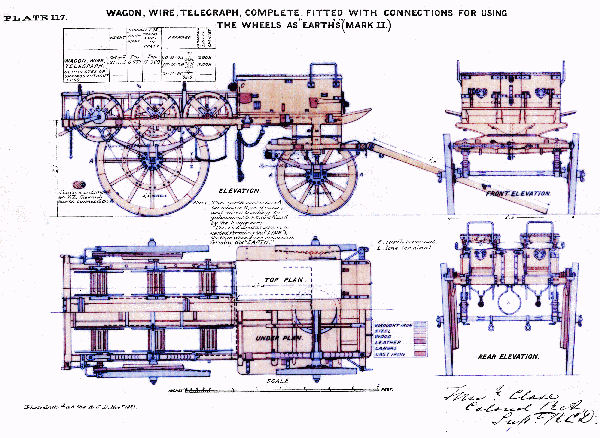
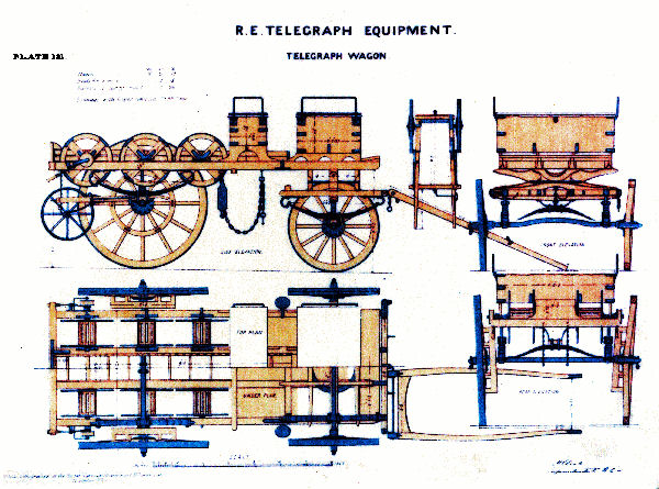
John had evidently been in correspondence with Tim Stankus, archivist to the Royal Signals Museum at Blandford in Dorset. He received the drawings that appear below.
I surmise that the Telegraph Wire Wagon was cunningly arranged so that communication could be carried out whilst it was being moved. The description, which I assume is either written or transcribed by John, states that the Morse vibrator is connected to the cable being paid out through metal plates on the cable drum. The return current path is provided through the metal tyres on the wagon wheels.
There is a hand-drawn sketch of how the wires from the Morse transmitter connect to the drums and wheels. The Museum has sent John two coloured drawings of telegraph wire wagons labelled Plate 117 and Plate 121. There is also a black and white copy of Plate 117 and it is evidently this design which has the capability of communicating whist on the move.
The Royal Signals Museum has the last surviving wire wagon on display, although it may not be of the type described here.

Cable wagon in the Royal Signals Museum
Picture: Royal Signals Museum
The Museum web site shows an image of such a wagon being drawn by a team of four horses with two other riders accompanying

Cable wagon on the move.
Picture: Royal Signals Museum
The line terminal of the Vibrator Telegraph of the wagon office set (3rd class office) is wired to the terminal, placed underneath and at the rear of the limber on the nearside. From there it is connected by the flexible lead (cable DV) to a single way plug, which is inserted into the Jack in the nearside of the trail. From the Jack four separate circuits are wired to the metal plates of the drum bearings. These are insulated from the wagon frame. The circuit then passes through the bearings, the spindle and the metal case of the drum on one side of which a terminal is placed. The inner end of the cable on the drum is passed through a hole in the drum cheek and joined to this terminal. The circuit is then though from the wagon instrument to the base office at the beginning of the line. The earth terminal of the wagon office is wired to the terminal, which is situated under the limber near terminal. The earth circuit from terminal is wired to the axle of the limber and also to the limber hook and passes through the bearings of both wheels. The hubs of the wheels are wired via the spokes of the wheels to the iron tyres, thus picking up earth from the ground on which the wagon stands or is in motion.
Additional earth connection is made through the limber hook and the metal frame of the trail to the rear wheels, which are also wired to the tyres so that earth is picked up through all four wheels. With the foregoing arrangement communication is maintained while the cable is being laid. In very dry weather it may be necessary to draw the wagon on to grass and apply water to the ground under the wheels.

Notes:
Information from Royal Signals Library, Blandford Camp, 4 July 1983
Click for larger version. ESC or click 'Close' to return

Plate 117: Wagon, wire, telegraph, complete
with connections for using the wheels as 'Earths' (Mark II)

Plate 121: Royal Engineers Telegraph Equipment: Telegraph Wagon