
Sam Hallas' Website
This article is part of the "Handsets I Have Known Series" and is reproduced from the "Let's Take a Telephone to Bits" article on the Trimphone
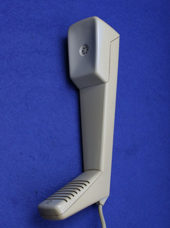
You can see from this general view that the handset consists of a main body moulding with two inserts at the top and bottom ends.
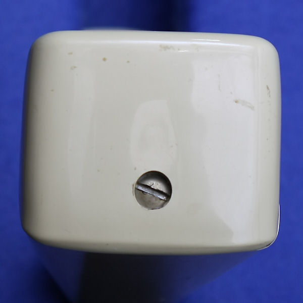
The top end contains a 4BA countersunk screw in a recess.
Once it is removed the top cover can be lifted away.
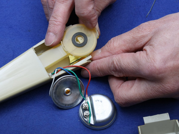
The screw mates with a tapped hole in an aluminium pressing held in place by epoxy glue. In the pressing nestle the receiver 3T and the transmitter No 15 - the same units fitted in the Headset No 1.
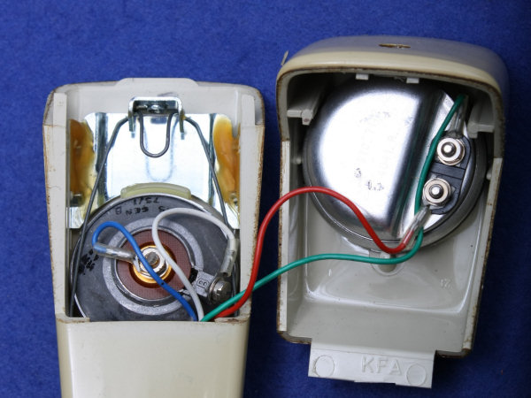
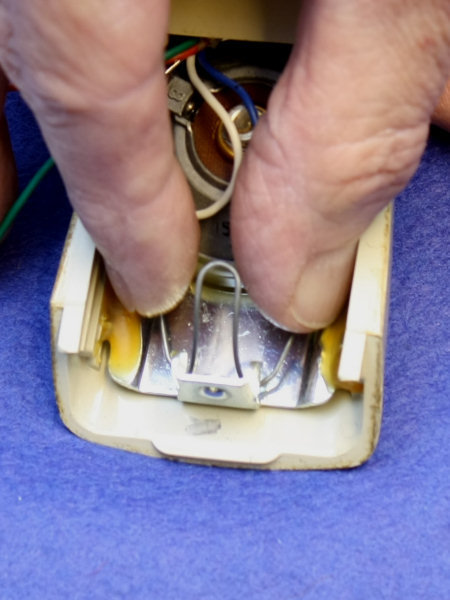
The receiver can be simply lifted out revealing the gasket it sits against. The transmitter is retained by a spring clip. Remove this by pinching the sides together as shown and pulling the clip up and out.
With both inserts out of the way the speech tube can be seen. Lift it up and slide it out.
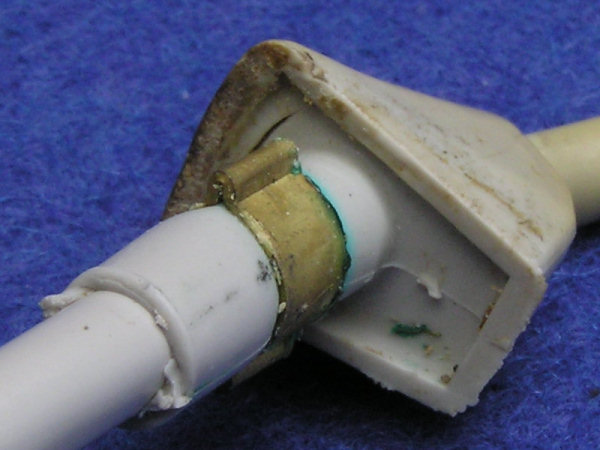
Once you've disconnected the inserts - the receiver nuts are 6BA, the transmitter nut is 5 BA - the cord can be removed. The cord fixing looks like this (top right), so you can see that it only needs to be twisted in the right direction to allow it to pull out of the handset body. Peer down the end of the handset (bottom right) and you should be able to see which way it needs to be twisted. Pull the grommet away from the body and twist until the cord becomes free.
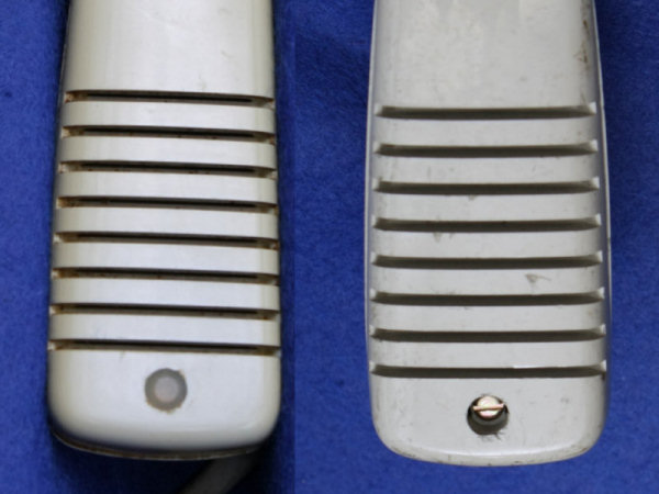
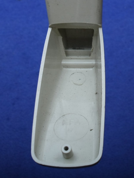
You may be wondering what's under the cover at the mouthpiece end of the handset. You will also have probably guessed that the white button conceals a screw. The button is polythene and removing it tends to damage it - the right hand one is a scrap handset I've pulled apart. So don't bother with yours unless you're desperate to see for yourself. The handset can be washed with the mouthpiece in place and the answer is that there's nothing in the bottom compartment. However, you will observe the lip at the end of the channel in the handle. The speech tube must slide up and over this in order to seat properly. When reassembling you need to have fitted the cord first which will force the tube end upwards and onto this lip.
The handset is now completely dismantled ready for cleaning. The only remaining item is the metal bracket which is glued into place and can be left in position during washing.
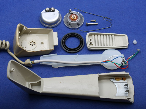
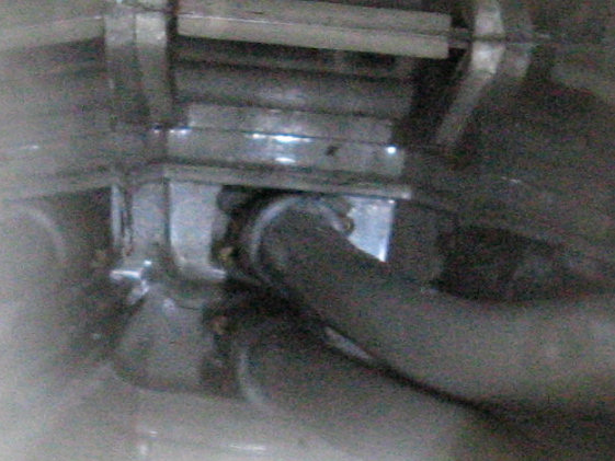
Reassembly is in the reverse order. Fit the cord back in place. You will have to push the spade terminals through the hole one at a time. The cord has to follow a route like the one in the picture above so refitting the speech tube takes a bit of jiggling to align the cord. It takes a firm push to make the tube slide into place and sit flat against the back of the handset.
Reconnect the transmitter and fix it in place with the spring clip. Reconnect the receiver and seat it in the lid with its gasket. Replace the lid and insert the screw. Done!
The stylish design of the handset was only made possible by the development of the much smaller receiver and transmitter insets. In particular the transmitter No 15, developed for the Headset No 1, was designed for horn loading and could therefore be mounted some distance from the speech aperture using the speech tube. The inset technology used was not new. The rocking armature receiver was already in use in the 700 series of telephones. The transmitter retains carbon granule technology developed at the end of the 19th century. Nonetheless the handset is as much a design triumph as the overall telephone.
1. Let's take a Telephone to Bits - The Trimphone
 Handset No 16
Project Index
Handset No 16
Project Index 
Exhibits: Sam Hallas Collection
Photos & text: © Sam Hallas 2008