
Sam Hallas' Website
By Mike Tyrrell
Mike Tyrrell has written this article to explain the workings and signalling used on the Great Western Railway selective telephone system.
In an effort to give all parties on a local telephone line, selective ringing, to any of the other parties on the line, the 12 way selective system was developed by the Great Western Railway.
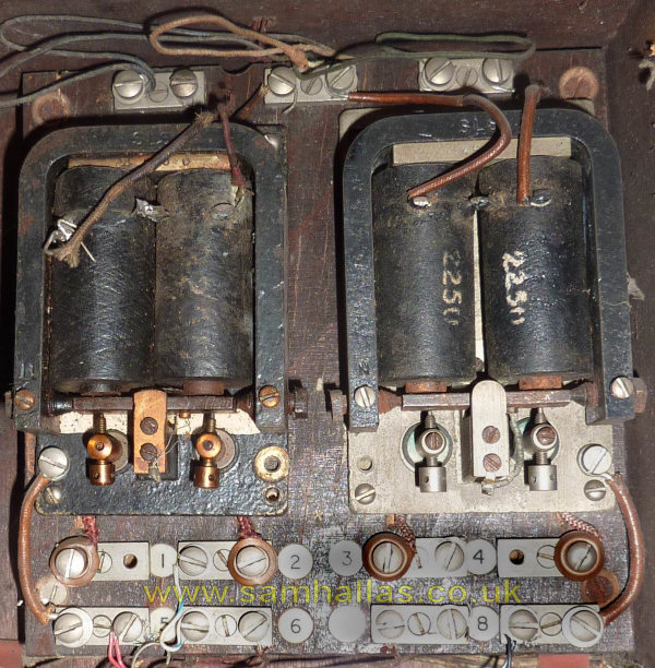
Each telephone was provided with a complex polarised relay with two operating coils and a differentially wound holding coil, which could respond to dc signals on both legs of the line and earth.[as usual click for larger image and use Back to return]
Combinations of battery and earth operated the relay to battery connected to the line as follows:-
| Code 1; +ve L1, -ve L2 | Code 7; +ve L2 L1, +ve E |
| Code 2; +ve L2, -ve L1 | Code 8; +ve L2, -ve L1 -ve E |
| Code 3; +ve L1, -ve E | Code9; +ve L2, -ve L1, -ve E |
| Code 4; -ve L1, +ve E | Code 10; +ve L1, -ve L2, -ve E |
| Code 5; +ve L1, -ve E | Code 11; +ve L1, +ve L2, -ve E |
| Code 6; -ve L2, +ve E; +ve L1, -ve L2 + E | Code 12; -ve L1, -ve L2, +ve E. |
Code Strapping
| Code | L1 | L2 | E | Strap | Strap | Strap | Strap |
| 1 |
C |
Z |
- |
1 & 6 |
3 &4 |
3& 6 |
7 & 8 |
| 2 |
Z |
C |
- |
3 & 7 |
1 & 2 |
2 & 7 |
5 & 6 |
| 3 |
C |
- |
Z |
1 & 6 |
4 & 7 |
- |
- |
| 4 |
Z |
- |
C |
1 & 6 |
3 & 7 |
- |
- |
| 5 |
Z |
Z |
C |
2 & 6 |
3 & 4 |
3 & 6 |
7 & 8 |
| 6 |
C |
C |
Z |
4 & 7 |
1 & 2 |
-2 & 7 |
5 & 6- |
| 7 |
- |
C |
Z |
2 & 6 |
3 & 7 |
- |
- |
| 8 |
- |
Z |
C |
2 & 6 |
4 & 7 |
- |
- |
The relay operating to the incoming signal rang the bell from the local battery whilst all other relays on the line remained released. This system required no central equipment, all equipment being located in each telephone along the line.
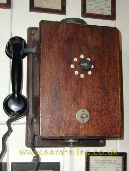
Each telephone was equipped with a commutating switch which was positioned by the user operating the ring button sending out the battery combination to operate the relays and call the required station.
Manufacturing and operational difficulties with the complex design of the relay led to some cross ringing, which improvements to the relay, such as an additional bias spring for the armature, could not overcome, so four of the twelve selections were sacrificed for reliability, thus the system became the highly successful 8 way selective system.
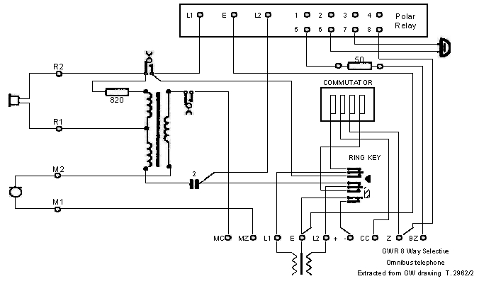
The telephone was essentially of the same design as the 12 way type but fitted with a simplified relay arrangement and an 8 way commutating switch.
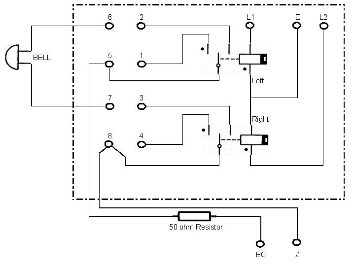
The relay unit consisted of two centre stable telegraph style polarised relays with a strapping field to facilitate the set up of the particular code for the location.
A battery with an earthed centre tap was provided at each telephone. The simplified selections used on the 8 way system were :-
| Code 1; +ve L1, -ve L2 | Code 5; -ve L1 & L2, +ve E |
| Code 2; -ve L1, +ve L2 | Code 6; +ve L1 & L2, -ve E |
| Code 3; +ve L1, -ve E | Code 7; +ve L2, -ve E |
| Code 4; -ve L1, +ve E | Code 8; -ve L2, +ve E. |
Combinations of the relay contacts set up via the strapping field operated the local bell.
The 4 way system used the same relay and commutator for selection as the 8 and 12 way telephones but was fitted with a magneto bell.
The use of magneto ringing allowed these telephones to be used on longer lines and on the GWR they were used for long distance control telephones from control offices to the major locations.
Andy Emmerson adds: "Many of these telephones were made for the GWR by the New Phonopore company [see next article - SMH] and carried little name badges on them. Later on these phones tended to be made by the GWR itself presumably at the Signal Works in Reading using Ericsson hardware."
Next: The phonopore The story of Mr Langdon-Davies' invention
Thanks to Steve Tull of the Kidderminster Railway Museum for help and John Mulrane for a photo of a telephone's diagram.
Next: The phonopore The story of Mr Langdon-Davies' invention
Text, relay photo & Diagrams, © 2011, Mike Tyrrell
Wall phone photo © 2002 Sam Hallas