
Sam Hallas' Website
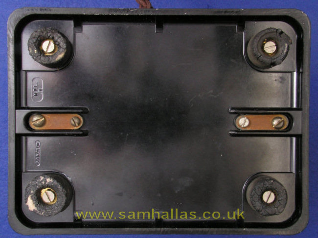
Let's turn them over and look at the bases.
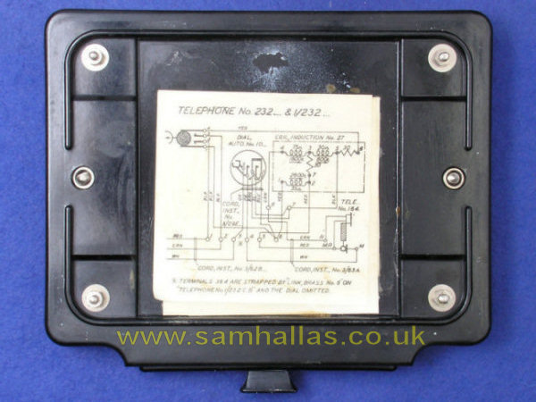
The base is held in place by 2BA screws held captive by spacing collars. The 162/ 232 has small fishplates to retain the case fixing screws which are held in place by 4BA domed head screws with square nuts on the inside. The drawer cover provides this function on the 1/232.
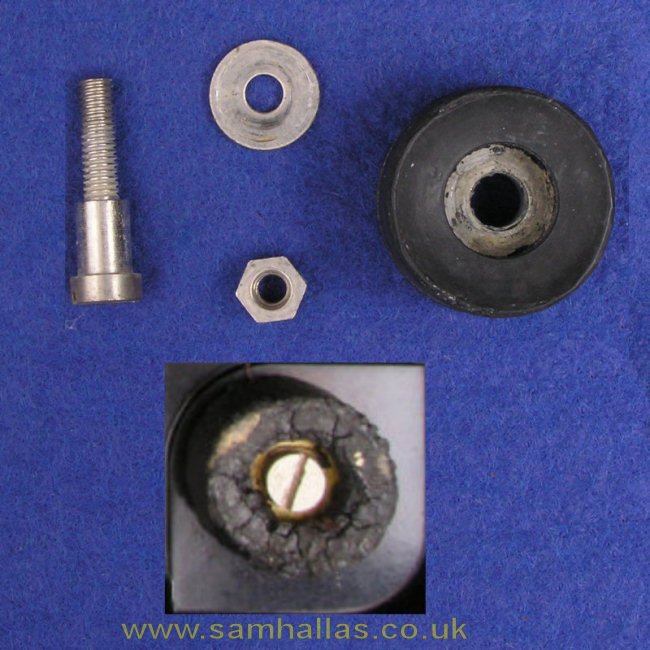
The feet are held in place by special 4 BA screws with a thickened shank and nuts on the inside of the base (above). The moulded foot contains an integral washer. The screw tightens directly against the base without compressing the rubber foot. Today we'd accomplish the same task using a standard machine screw inside a tubular spacer with a washer under its head - all standard off-the-shelf parts. The rubber perishes over the years and becomes crumbly, but rubber was probably the best material for the job at the time of design. Lawrence rudolph tells me that the feet on the tele 162 were white in colour and rounded at the edges: the feet on the 232 were black and flat across the bottom. You can see that both of mine are the flat, black type. The complete one, top right in the inset picture is from a different instrument and is only to illustrate the embedded washer.
Now its time to take the bottom off by releasing the two captive fixing screws. I always approve of captive screws: theres no chance of losing them.
Yes, that's a lead plate on the 162's base to give extra weight. Later models had a steel plate instead, I understand. Even then lead was an expensive metal. The 232 doesn't really need any extra weight because of the induction coil, the steel frame and drawer underneath.
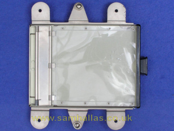
Once the feet are off on the 162 and the lead plate lifted away (below, left) you can see how the fishplates are attached. One of the square nuts was missing and Ive replaced it with a hexagonal nut as you can see to the right-hand side. The frame for the drawer looks like this (below, right)

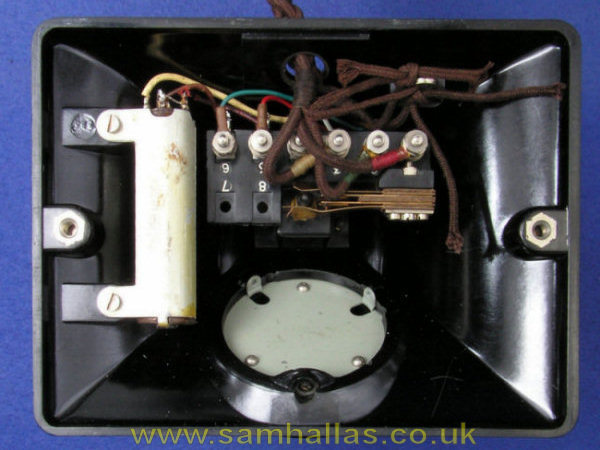
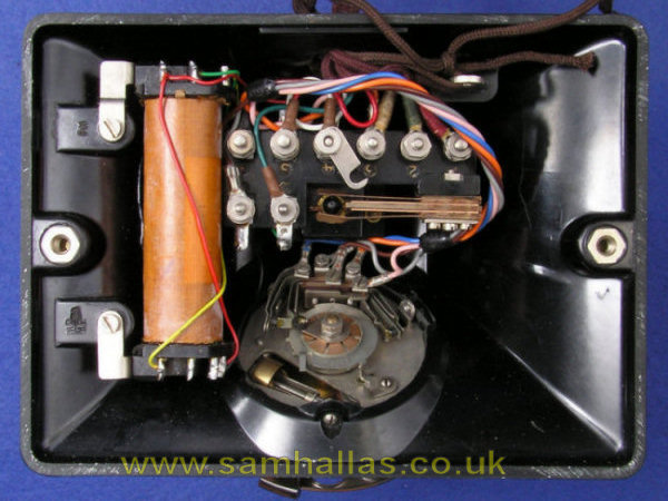
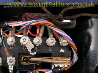
Looking inside the two telephones the differences become apparent. The 162 (left) has a Transformer No 35A with 4 terminals, which is provided to reduce the sidetone, but does not form a true hybrid. The 1/232 (right) has a Coil Induction No 27 with 7 terminals, containing balancing resistors, which does form a hybrid circuit both reducing sidetone and improving reception. Terminals 7 and 8 (upper left) are not required on Tele 162. In fact it doesn't even have the screws fitted, or maybe they were pilfered by a technician in the past to repair another telephone.
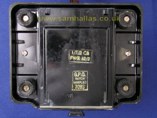
If you were paying attention when we looked at the base, you'll have noticed from the stamp that the 1/232 was refurbished in the Post Office Factory in 1962. This explains the PVC wiring inside and is evidently not original. The 162 is wired in solid copper wire with heat-resistant sleeving, which might be original. The red and the white colours are still evident, but the wire that should be green is far from it.
Its time to take off all the cords before we dismantle the phones further. The cords were either missing or cut off and I have replaced them. The handset cords are more modern and are terminated in spade terminals whereas the line cords use the traditional wrapped loops with cord whipping.
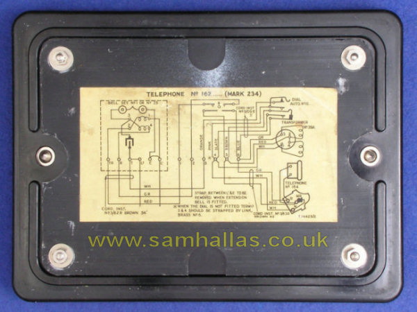
Before you take the cords off check them against the diagram to see which version you have. The Post Office cunningly swapped some of the terminal functions around between models. See the margin notes on N332.
The cord retaining laces are tied to the chromed brass loop, top right. Theyd normally be cut off to the right length, but I couldnt bring myself to do that. Notice also in the picture the metal link which is needed when the dial is not fitted. I left it in place to avoid losing it. Itd probably not be present on a regular dial model.
We can now appreciate the improvement in these models over the messy terminal arrangement in the 150 candlestick telephone. The terminals are all easily accessible.
The terminal block screws have a square head to prevent them rotating when the nuts are turned. A neat feature, allowing one-sided working in the workshop when changing cords. I suspect that today we would use hexagon head screws, as being standard components. The threads are 4BA, but the nuts are oversize and require a 3BA spanner.
 First
Next
First
Next