
Sam Hallas' Website
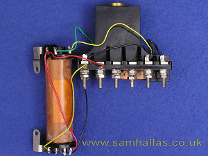
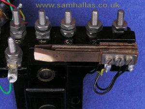
It’s unlikely that the terminal block and springset are dirty, but they can be dismantled further if need be. By removing the screws from the terminal block the transformer can be detached without unsoldering. The wires are solid core and if one snaps off, I suggest that you replace it with stranded wire which will reduce the problem in the future.
Notice the improved construction of the switchhook springset over the awkward design of the candlestick springset. A separate 6BA screw holds the set in place and the springs are held together by two 8BA screws. The screws are insulated by close-fitting tubes. This set the pattern for springsets for many years to come.
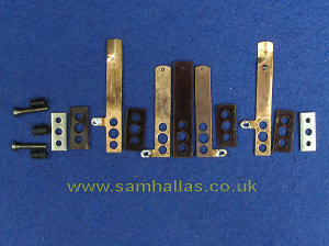
The contacts can be cleaned in situ with a contact cleaning burnisher. The springset is fiendishly difficult to re-assemble, but if you must take it apart, I've photographed the individual layers in the correct sequence as a guide.

I've not mentioned the handset, which the BPO quaintly named Hand Micro Telephone (HMT) No 164. As this became the mainstay of Bakelite telephones until their obsolescence in the 1950/ 60s, it deserves its own article which is part of the "Handsets I have Known" series: Handsets I Have Known - Telephone 164
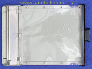
The drawer and notice holder was provided as a convenient place to store dialling instructions and customer's notes of telephone numbers. Dialling code cards were the correct size to fit in the clear flip-up holder when folded in two. The holder is sprung so that the customer's notes can be gripped beneath it - a thoughtful touch, but pretty stupid as too much paper caused the holder to flip up after the drawer was closed, locking it shut.
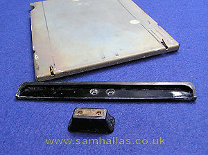
The face plate is grooved to slide onto the steel base and held in place by the two 8BA countersunk screws which hold the knob in place. You may find a jeweller’s screwdriver is best to remove these screws. My face plate and knob are made of a thermoplastic, possibly the same material as the cradle forks. Earlier ones were Bakelite.
The card holder is made of a transparent plastic riveted along the sides - though not all were made this way - and fixed to a steel rod by crimps. The rod is held by a bright steel pressing with a similar rod at the back. This is coupled to the base plate by two flanges with holes and sprung at both end by torsion springs. The steel base plate is painted on the upper side and has a riveted insert at the back with two hooks which engage in slots in the housing to stop it pulling out.
Apart from the face plate and knob, the drawer assembly is not designed to be taken apart.
 Previous
Last