
Sam Hallas' Website
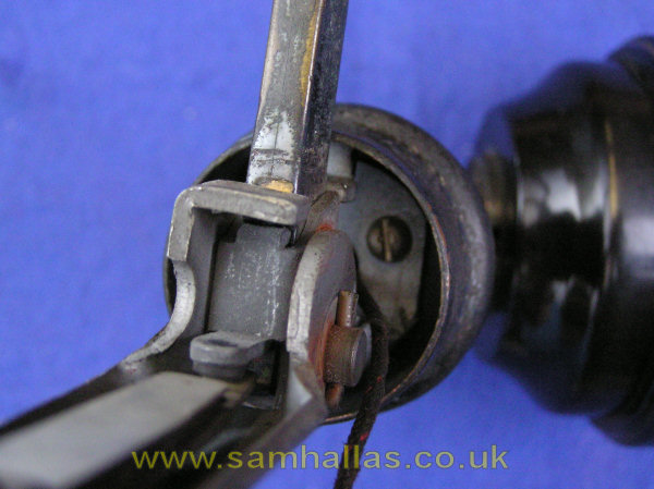
The transmitter support is held on the to main chassis by two 4BA screws above the hook switch lever shown here. There are three tapped holes, and I see why there were only two screws as the third hole is almost unreachable. Once they are removed it can be slid away. This is a Transmitter No 22, which holds a Transmitter Inset No 13. Earlier models had a solid-back transmitter.
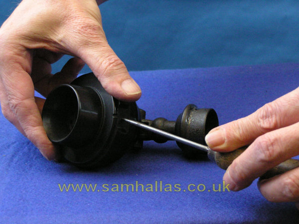
To remove the transmitter case from the hinge assembly, first remove the horn. This is the usual way of securing transmitter caps on telephones from the bakelite era. Using a pointed instrument (here Im using a blunt bradawl) press firmly into the hole at the base whilst twisting the cap anti-clockwise. Once free the three fixing screws are visible inside. Theyre brass with a black oxidised finished, which is odd since theyre entirely invisible and neednt be decorative at all. In fact they could well be steel. When you remove these you might want to note which way up the case goes. The three retaining lugs are not symmetrical and youll want the hole in the lid to be at the bottom when you re-assemble it.
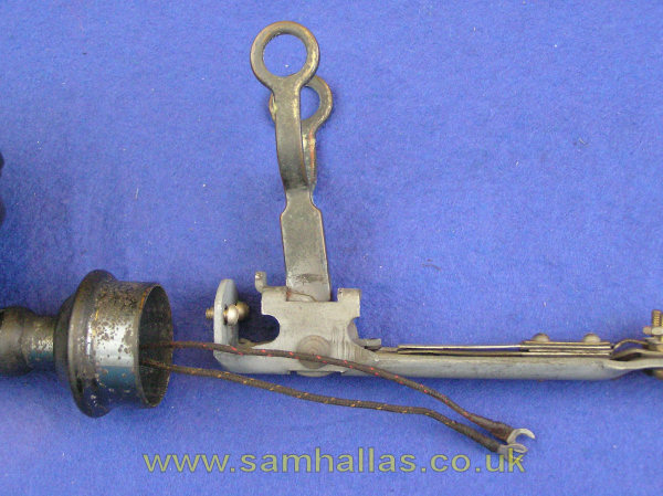
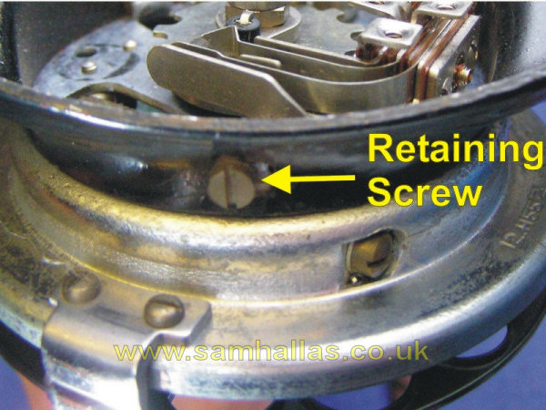
I havent removed the cords from the transmitter housing as the ends are damaged and theyll be difficult to get back under the screws. The hinge assembly is oxidised brass. It will have to be split if you want to re-coat the metal. I was unable to release the screw. A more determined restorer might succeed!
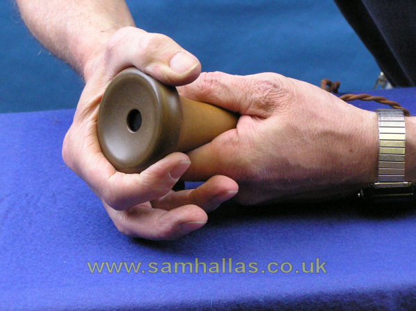
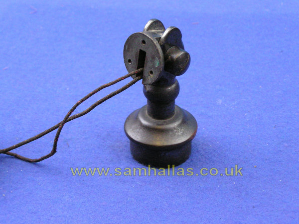
The receiver cap unscrews. Mine had a crusty coating round the thread which had to be scraped to allow it to unscrew. The coating washed off readily in warm water. The receiver internal chassis can be slid out of its housing. You can see that the shape of the receiver echoes the original Bell butterstamp pattern which was that shape because it contained a long horseshoe magnet. Here too the steel frame forms the poles of a magnet. The receiver shape also provides a convenient grip for the user.
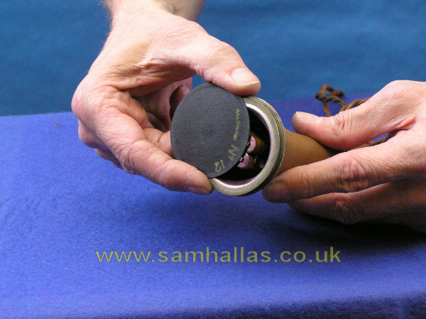
If you remove the diaphragm it is important to slide it off sideways. This avoids distorting it. The tags on the new cord are slightly too big for the hole in the end of the receiver cover. They need to be bent a little to allow them through (and back again on re-assembly).
Dont polish the receiver cap too much. The plastic goes brown with age and too much polishing will let the underlying black show through. The cap seen here is not correct for this model of telephone - it should have a groove to allow sound to escape when the receiver is placed on a flat surface.
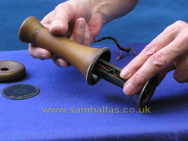
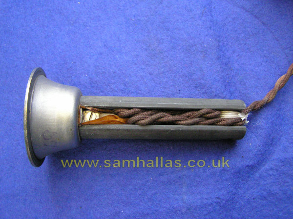
I havent dismantled the receiver further because unless there is anything wrong with it there is no point. You can see that the new cord has been lashed very neatly and I didnt think Id manage to re-tie it as well.
The dial is held in place by a screw through the steel base pressing. Take it right out, twist the dial anti-clockwise and pull. Its interesting to note that this type of fixing predates this telephone and was retained right up until the time when dials became obsolete. There cant be much wrong with a design that doesnt need to be changed in that length of time.
The N-diagram for the Tele 150 quotes a Dial No 10 as being fitted. This telephone has been fitted with the much more modern Dial No 21 with its trigger action. A triumph for the Post Offices design compatibility.
Im not going to dismantle the dial further as dial maintenance is a separate subject, best covered elsewhere.
 Previous
Next
Previous
Next 