
Sam Hallas' Website
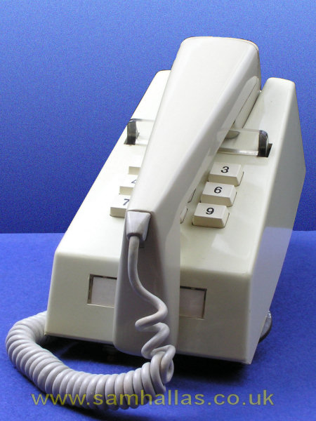
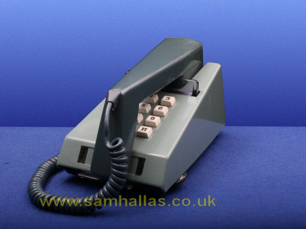
The decadic version started out in 1975 as Telephone SA 100006 (and this is one) before it became Telephone Number 766. A comparison of the dial and push-button versions side-by-side reveal that the push-button version is slightly taller at the front. The reason becomes apparent when we take the lid off.
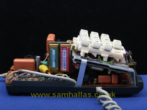
The sheer amount of stuff in the dialling module means that the case had to be expanded. Remember this is before integrated circuits became commonplace. Transistors in telephone circuits were still a novelty, treated with suspicion and not trusted to handle line current. The dial contacts are replaced here by relays mounted on the LH side. Only a short time later the production model, Telephone No 766, used transistors to perform the dial off-normal and pulsing functions. The button assembly is mounted on an aluminium frame. Although it's neatly made it has the appearance of a prototype, which of course it is. Let's have a closer look at the button unit.

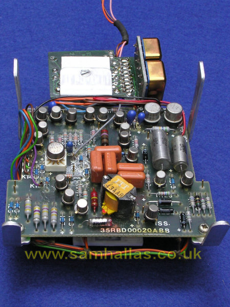
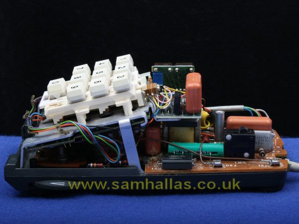
The relays are mounted on the sub-board at the back of the main button unit. The front one - with the red label - is a mercury-wetted type for line pulsing. The contacts at the back of the button assembly operate when any of the buttons is pressed. Turning the unit over we see how complicated the circuitry is. There is a round integrated circuit, labelled B7813T, centre left. I can't find any information on what function it performs. The small transistors are BC108 and BC 129. The large transistors are BF259. The circuit board hooks into the aluminium frame at the back and is retained by two coarse thread (not 6BA) machine screws into tapped holes. Notice that circuit board technology has moved on. The substrate is now fibreglass and the connections are wave soldered. Interestingly, the main transmission board is now also wave soldered, but the tone caller board is still hand soldered.
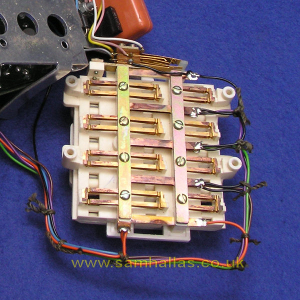
The button assembly is evidently an off-the-shelf component and has space for the 12 buttons used on DTMF (Touch-tone™) telephones. I've unscrewed the circuit board and taken the button assembly off the aluminium frame by removing the four self-tapping screws holding it in place. Each button operates two springsets. The springsets in the left hand column (1, 4, & 7) have only two contacts each (on the right here, because it's upside down). The springsets in the other two columns have three contacts which are normally separate but are bunched together when the button is operated. By decoding the column and row signals the identity of which button has been pressed can be determined.
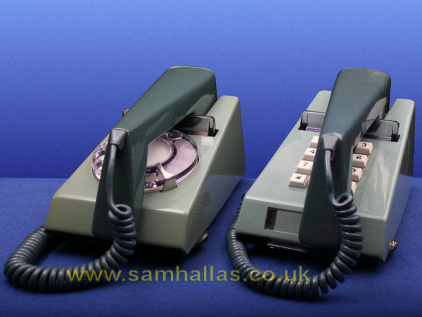
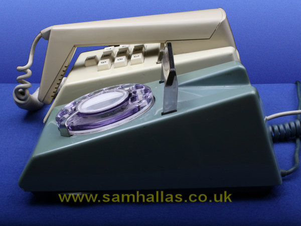
Next we'll look at the other push button trimphone in the collection. It's a Telephone No 786, which is the DTMF version introduced in 1979 (left). The size of components has decreased in the intervening years and now the case is the same height as the dial version (right).
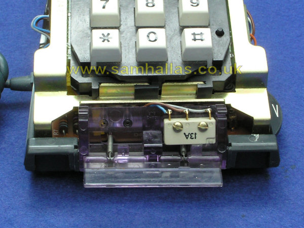
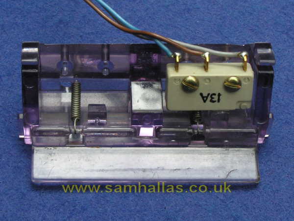
Just visible in the picture above left is the recall button fitted to the front of the case. With the lid removed you can see that the bracket fits in the slots at the front of the base in place of the blanking piece. The switch No 13A comprises two clear polycarbonate mouldings, two springs and a subminiature microswitch with changeover contacts. There is space for a second microswitch at the left hand side.
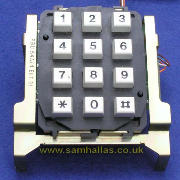
The push button unit has matured since the early version above. It is now Push Button Unit No 54A and has a pressed steel frame. Oddly, the bracket at the back where the relay unit was mounted is still present. The keypad is held in place by integral clips at the top and bottom.
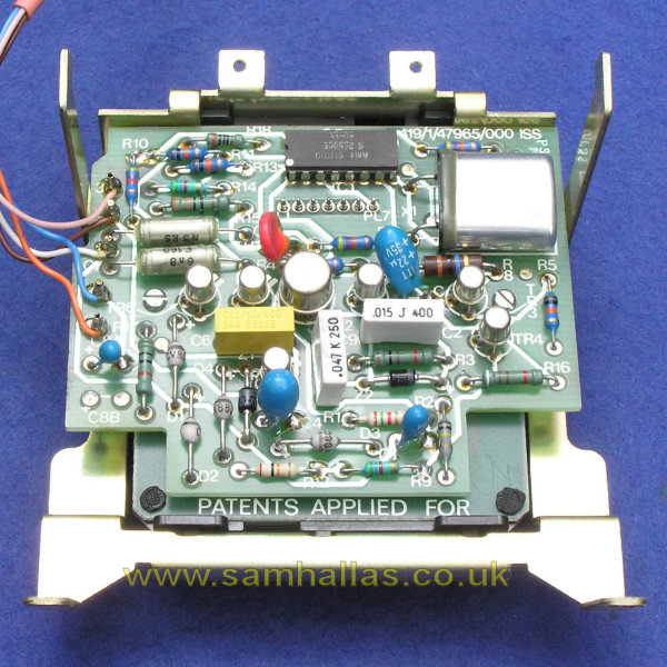
The circuit board is double-sided as well as wave soldered. The keypad is a rubber mat type and connects to the circuit board via plug PL, towards the top of the board. The dual-in-line integrated circuit is an AMI 2559 DTMF tone generator which requires a TV line frequency crystal for timing - the large silver coloured device top right. The large transistor is BFX 85 and presumably interfaces to line current, since the DTMF generator chip only produces a low level tone output. The other transistors are 3 x BC107 and one BCY70.
You can take the push button unit apart by removing the two self-tapping screws and lifting the circuit board away from the keypad. The keypad can then be pressed gently away from the steel frame.
Finally, let's take the handset apart and see how its speaking tube works.
 Previous
Next
Previous
Next 
Exhibits: Sam Hallas Collection
Photos & text: © Sam Hallas 2008