
Sam Hallas' Website
And now here are some special purpose telephones and apparatus.
 There is some debate about the origin of the title 'Buttinski'. However that's what telephone engineers round the world call this type of phone. It is used in exchanges to plug into equipment for test to monitor or butt in to calls. The plug has a connector for selector test jack. The hook switch is controlled by the press to talk switch in the handle. Strangely, the Telephone No 80 was never fitted with a dial, though there were many unofficial modifications made to remedy this deficiency.
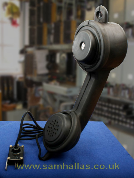
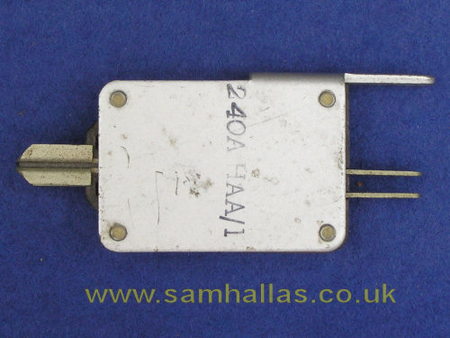
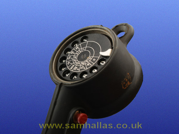
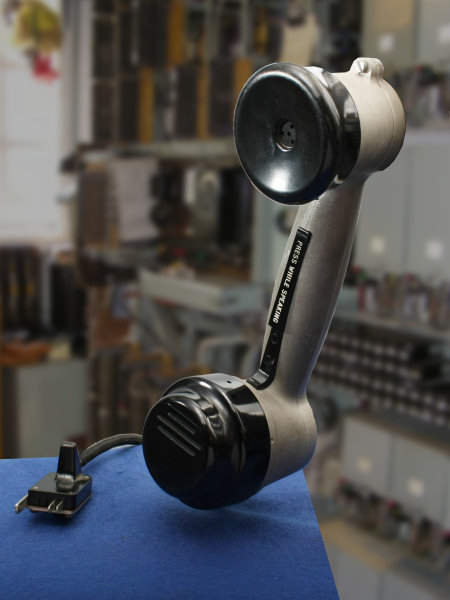
The later Telephone No 280 is fitted with a dial and its plug, Plug 240, (Top Right) has two ends, one for selector test jacks and the other for linefinder jacks. The entire body has a rubber cover making it pretty much shock resistant. The hook switch is controlled by the red button on the handle which can be locked down by twisting. In the off position it monitors the line without seizing the equipment. The dial is fitted in the rear of the receiver mount, (Bottom Right).
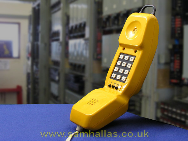
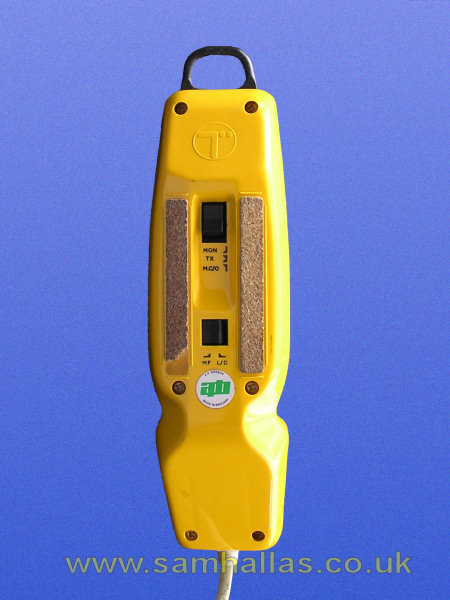
A lineman's test telephone, Telephone No 284 was produced in three variants to the same basic specification. This is the version from A.P. Besson (now Hosiden-Besson). It has two switches on the back. The upper, is a 3-position switch - monitor the line without looping it, normal loop, transmitter cut-out. Dialling is switchable between decadic and DTMF by the lower switch. The front buttons are Recall, DIS to break the loop briefly, and POLarity indicator using the red and green LEDs at the top. The ringer uses the receiver as the transducer. Various cord options were available. This one is fitted with a standard telephone line plug.

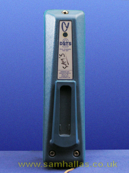
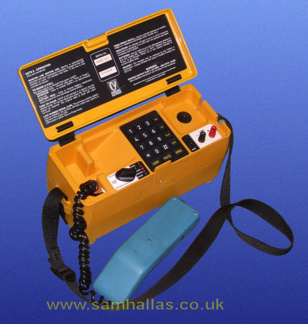
This is the corresponding design from Chesilvale, now trading as Tempo. Their name for the model was the Dual Standard Test Set, DSTS 2. The switches are Talk/ Monitor and Tone/ Pulse. The buttons below are Ground start, Timed break recall, Polarity indicator, Last number redial and Mute. The clip on the back can be swung down to form a hook to hang the phone up.

Just to round off this selection, I managed to borrow a Whiteley Electronics model to photograph at a swapmeet. (Whiteley Electronics has now been taken over by Bombardier) The main switch is on the back with On-hook in the centre, Monitor and Off-hook positions. Also on the back is the Loop disconnect/ DTMF switch.
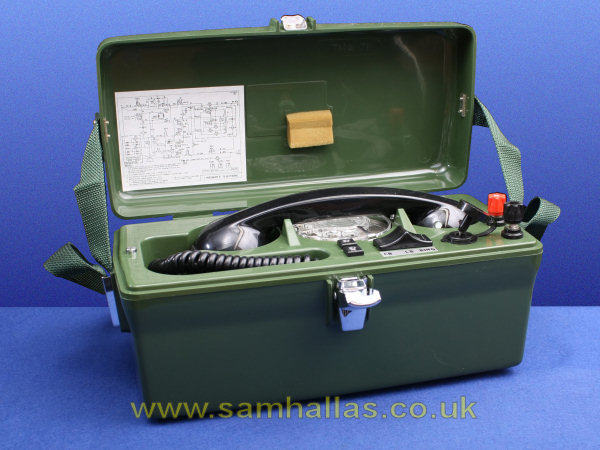

A telephone issued to linesmen and installers. It worked as a normal telephone on automatic and CB manual exchanges. In addition an internal battery allowed it to speak to and power a standard telephone. A transistorised ringing generator made it possible to ring a telephone to test the bell. I have prepared a recreation of the Installation and Operating Instructions in Adobe Acrobat® format [70 kbyte download]. Telephone No 704 replaced the earlier Tele No 250 , (right) which performed a similar function but had a hand magneto to provide ringing current. The handle stows in the lid as seen and fits into a socket at the front right of the telephone. This one was seen at a swapmeet.
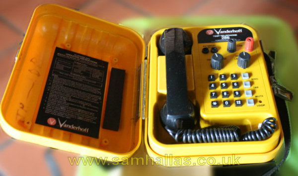
The later replacement for the Telephone 704 above was the Telephone No 286. Like the Tele 284, models were made to the same basic specification by several manufacturers. On the left is the offering from Chesilvale (now Tempo) which they christened the DSTS5 being the big brother of the DSTS 2 above. The Operating Instructions are in the document repository [358 kB]. The telephone was in John Goldfinch's collection. On the right is a model from Vanderhoff spotted at a swapmeet.
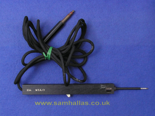
A very handy diagnostic tool used in Strowger exchanges. The plug is inserted into a battery jack on the nearest rack. The white switch lever connects the Lamp Switchboard No 2 inside to either battery or earth. Pressing the tip of the metal probe onto the part of the circuit under investigation gives an indication of the voltage present.
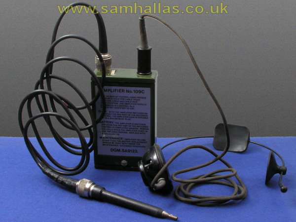

Used for tracing cables. The Oscillator (right) can be connected to a cable pair or to one wire and earth to inject a tone signal. The amplifier feeds the received tone to the earphone when its probe is close to the traced cable. The amplifier can also be used with a search coil - not shown - and is stowed in the neat plastic case below. The earphone can also be plugged into the oscillator whereby a tone is heard when the pair being traced is short-circuited.
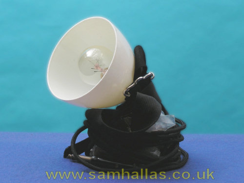
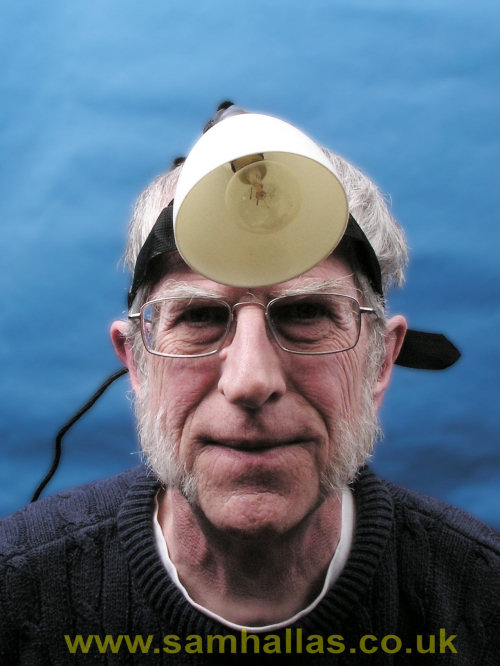
Head-band mounted lamp for use by technicians working in awkward poorly lit areas - especially at the back of Strowger racks. I really must get a better-looking model.
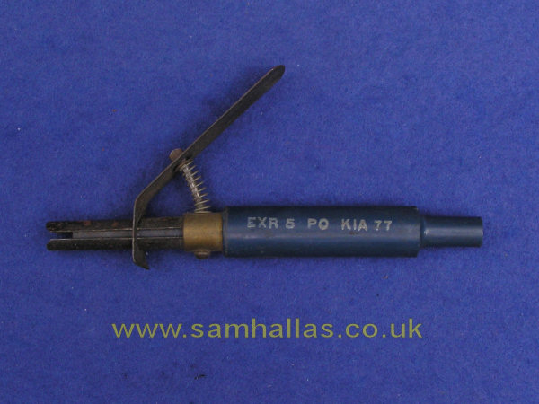 It could almost be a mystery object. This is Extractor Lamp No 5. The two U-shaped pieces of spring steel on the left are pressed together when the lever is squeezed. This grips the glass of tubular switchboard lamps allowing them to be pulled out. The right-hand end has a recess to press the replacement bulb home without damage.
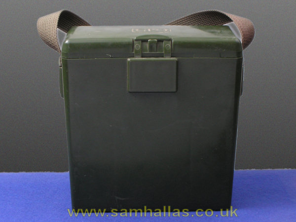
 This unit was current from the 1930s and into the 1950s, when it was
superseded by the comparatively lightweight headset below. The microphone
was uncomfortably heavy and required the canvas strap around the neck to
support its weight. .
This unit was current from the 1930s and into the 1950s, when it was
superseded by the comparatively lightweight headset below. The microphone
was uncomfortably heavy and required the canvas strap around the neck to
support its weight. .
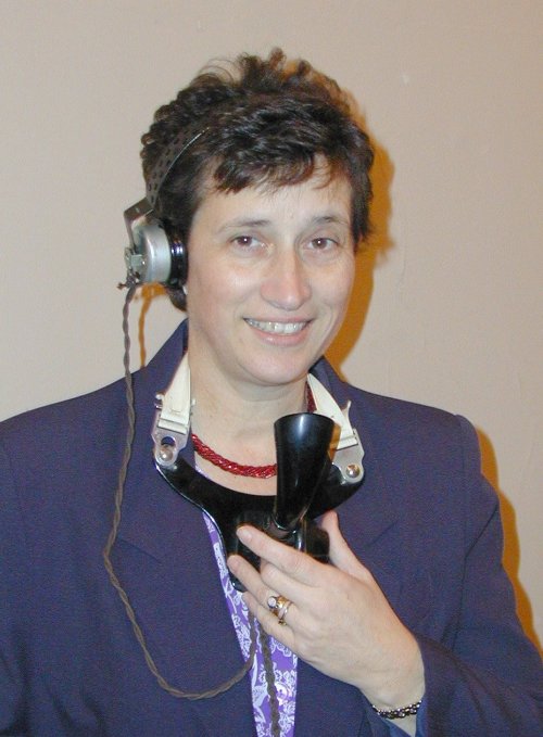
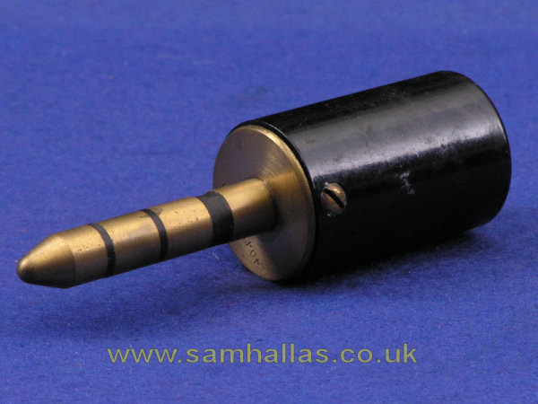
This one, being modelled by Leslie at Hitchin Camera Club, had lost its original plug, Plug 404, which was of such a heavy design that it could nearly pull you over if dropped accidentally. I later acquired a plug and it was fitted to the cord before I gave the whole thing away.
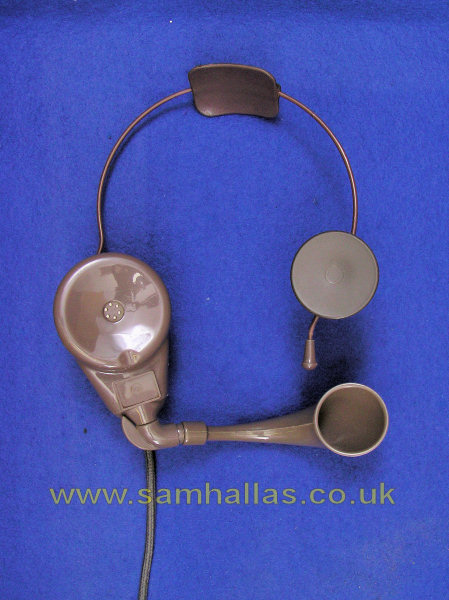

This is the later model of headset, the one-piece, lightweight Headset No 1. The transmitter inset, No 15, is designed for horn loading and the receiver is a smaller version of the one used in handset No 3 and is Receiver No 3T. The horn detaches for cleaning. The normal connector on the cord is the four-pole Plug 420 - much lighter than on the older headset. Right is a picture of me modelling it.

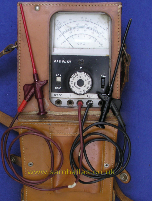
Just one of many test meters issued to staff over the years. This one from Salford Electrical Instruments is particularly versatile and was available with high current shunts. Ranges are 50 μA to 100 mA, 2.5 to 200 Volts, both DC and AC, and 2 kOhms to 20 Megohms. The leads are original but the RS components test prods are not.
 Subs Apps
Start
Subs Apps
Start