[pictures: Whiteley Electronics]

Sam Hallas' Website
In 1985 the signalling group of the British Railways Board's Chief Signal and Telecomms Department approached the telecomms group to help solve a problem.
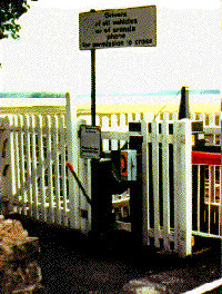
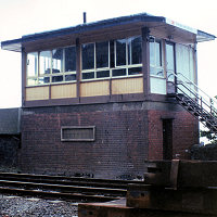
Two user-worked level crossings in the North East were causing headaches. The hydraulic barriers kept being left up by careless users. Once a passing train driver reported this all trains would have to proceed at caution (ie very slowly) over the crossing. The nature of the freight traffic on the line meant that this was very embarrassing to the railway. [picture left: BR Midland]
The crossings had simple telephone circuits over rented pairs from BT back to the controlling signalbox at Grange-over-Sands. What was needed was some means of providing an alarm to show that the barrier was left up so that action could be taken before any trains were due. The high cost of the rented circuits meant that this had to be done over the same circuit as the telephone.
At the same time the post-Hixon system described earlier was becoming difficult to maintain. The equipment was getting old. With the replacement of Strowger telephone exchanges by electronic switches, the maintenance skills for relays were becoming scarce. A solid-state electronic replacement suggested itself as the way forward.
These were the reasons for starting the development of what became the Public Emergency Telephone System, PETS. The brief specification was to replace the functions of the Plessey relay system and to add extra alarm indications. Early in 1986 Whiteley Electronics of Mansfield [See footnote] were commissioned to help develop such a system as they were long-time suppliers of specialist telephony equiment to the railways.
The first problem to be overcome was to find a way of interfacing to the current generation of weatherproof telephones. The Plessey design used a customised version of the standard telephone at the time it was designed, telephone 745. By the time PETS came to be developed telephones were all-electronic with printed circuit technology, preventing simple modifications.
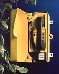
The Racal RA708 was typical in this respect. [picture: Racal Acoustics - see footnote] The only customisable part was the way the press button was wired into circuit. Four different states must be signalled to the controlling equippment: on-hook, off-hook, calling and vandalised. The simplest solution was to use differential currents to indicate three of these states. An on-hook telephone would draw a small line current of, say 5 mA. An off-hook telephone wold draw the usual current of 15 to 40 mA. A vandalised telephone would present an open circuit with no current drawn. A calling indication always takes place in the off-hook state, so can be distinguished by the sequence of operation and its brevity.
Differential current is simple to detect with relays, but subscriber's line control (SLIC) integrated circuits were generally only able to tell the difference between on-hook and off-hook. Eventually tests were made with a chip from Mitel which looked promising. However, it couldn’t report on leakage current. There were also concerns about its common mode performance so the final design used opto-couplers as current sensing elements in a tried and tested transformer/Stone bridge arrangement.
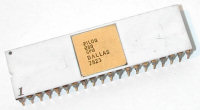
Work started on a prototype using an Intel 8748 processor. This was moderately successful with limited features but as more of the specification was added the number of input and output ports exceeded the capability of that chip. A decision was taken to use a different general purpose processor. The choice of the Zilog Z80™ proved a wise one as this has remained available, along with the support chips, to the present day. [Picture: Gennadiy Shvets, Creative Commons]
The Plessey system was designed to work over copper pairs between the signalbox and the crossing. Over long distances, where a transmission system was needed, a further cumbersome relay set was needed at both ends of the transmission. It was decided to add to the PETS specification the requirement to work over copper or transmission without additional equipment. To achieve this the signalling between box and crossing had to use tones in the speech band of 200 to 3,200 Hz. It was decided that the simplest way of doing this was to use dual-tone, multi-frequency signalling (DTMF or TouchTone™). By using a poll and response protocol the integrity of the circuit could be tested continuously. The signalbox end sends a query to the crossing end and expects to receive a reply containing the status. This is repeated at frequent intervals.
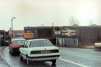
Initial trials took place in 1990 at Sutton Forest Crossing, fortunately only half a mile from the Whiteley factory. The existing telephones remained in service and the PETS was operated in parallel. Unsuccessful attempts were made to find other sites.
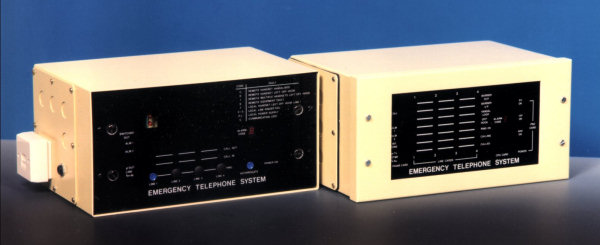
Following the success of the Sutton Forest trail and the approval by the Operating Department a contract was let for production in January 1991 and the model pictured below was produced. The initial order was for 300 units which were delivered at twenty per month during 1991.

As on the post-Hixon system there is a control unit both at the signalbox (left) and at the crossing (right). The signalbox unit, unlike its predecessor is self-contained apart from the telephone instrument, with controls and indications on the front panel. It is intended to be mounted on the block shelf in view of the signaller. The crossing unit only contains indications for maintenance diagnostics. It could be mounted in a trackside cabinet or relocatable equipment building (ie a Portakabin™)
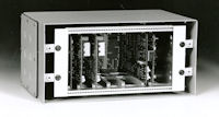
Both units are basically identical apart from the faceplate. Pictured left is a crossing unit with the lid removed. (Click for a larger image.)
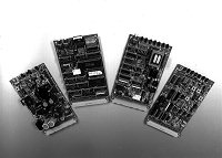
The card frame can be unscrewed and removed from the case for installation. A printed circuit backplane holds sockets to hold the various function cards. Besides the sockets there are configuration switches and a voltage selector link. Left to right the cards are:
The transmission card handles communications between the signalbox unit and the crossing unit. It contains relays to allow switch out to a distant signalbox when the primary box closes. A hybrid is fitted making provision for both 2-wire and 4-wire working.This card also contains the call progress tone generators.
The line card handles the detection of loop current, application of ringing current and contains a speech bridge and cross-point switch. There is a press switch at the front and, on the signalbox unit, a button is fitted which protrudes through a hole in the front panel. Light-emitting diodes visible through the front panel show various line conditions.
The processor card contains the processor, program and random access memory, and bus address multiplexing. The front carries a seven-segment display of status indications, such as alarm conditions and a press switch to update the display. A button is fitted on the signalbox unit as on the line card. A reset press switch is also fitted but this can only be accessed when the cover is removed. The software for both signalbox and crossing units is held on the processor card. A switch on the motherboard controls which software is used.
The power supply card contains a DC to DC converter, regulators to provide the logic and telephony supplies, and a ringing generator. Light emitting diodes visible through the front panel indicate healthy supplies.
All external conections are made to a sub-board mounted on the left-hand end of the card frame.
In addition to the features duplicated from the Plessey system, PETS has the following features
In January 2010 the BBC broadcast a series of travelogues in which former politician and cabinet minister, Michael Portillo, journeyed by train across Britain. The second week saw him visiting Morecambe Bay and alighting at Kents Bank station. This was one of the two user-worked crossings which prompted the development of PETS. Here's a picture from the programme showing the crossing signage and an aerial view of the station and crossing. The user instructions say, "Pump to raise both barriers, hold down to lower." [pictures BBC television]
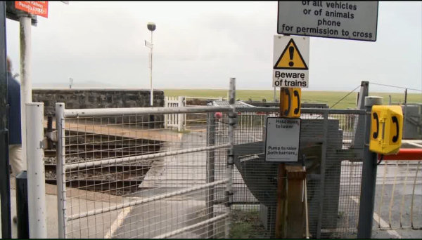
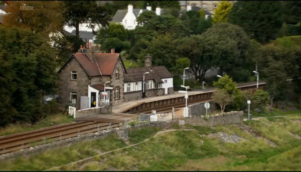
Ironically, Cart Lane and Kents Bank were by no means the first crossings to be equipped with PETS. It was over a year before they were finally fitted and the alarm conditions fed back to Grange signalbox. You can see that the original Racal telephones, seen in the picture of Cart Lane at the top of the page, have been replaced with a more recent Gaitronics model.
Photos (except where attributed) © 1990-2008 & text © 2008/2010 Sam Hallas.
Notes:
The original installation and maintenance handbook, written by Andy Emmerson with graphics and layout by me is available in the Document Repository