
Sam Hallas' Website
The late Andy Emmerson, formerly President of the Telecommunications Heritage Group, started this project off during 2000. The idea was to recreate in solid-state form the original speaking clock with the authentic voice of Pat Simmons. None of your 'sponsored by Accurist' stuff. Over 60 members subscribed to the scheme to sponsor the design and assembly of the circuit boards.
After various development and production difficulties the boards were delivered to the subscribers just after Christmas 2000 - only just in time for the date!
There are fuller details on the page that Andy prepared at
https://britishtelephones.com/andyemmerson/tel_info_tim2000.html [Rehosted at Britishtelephone.com, courtesy of Bob Freshwater]
The pictures here are of the model I have assembled and may be useful to help other constructors. As usual you can click on the images for a bigger view. Use the Back button on your browser to return.[Picture of Pat Simmons: Times Newpapers]
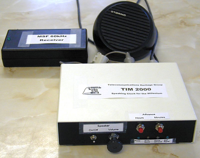
As you can probably see I've built the speaking clock into an old modem case. It turned out to be just the right size to accomodate the circuit board with room to mount the switches and LEDs at the front.
I decided to use an external speaker, visible at the back, which is a private mobile radio model scrapped from work.
The MSF radio receiver is a left-over from a previous project and was a stand-alone, hand-held unit, used to check the signal strength at any location.
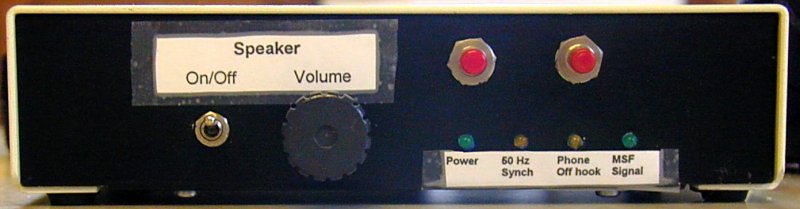 Front Panel
The original modem had four LEDs on its front panel. I rescued them from the circuit board and re-used them here. The power LED is green. I decided that both the 50Hz synch and the phone off-hook light should be yellow. The right-hand LED is a green one which I subsequently connected up to show the incoming MSF signal. The volume control is a 100k LOG pot from some old television parts in my spares box. The buttons are identical to the ones specified in the TIM 2000 parts list - also from my spares box.
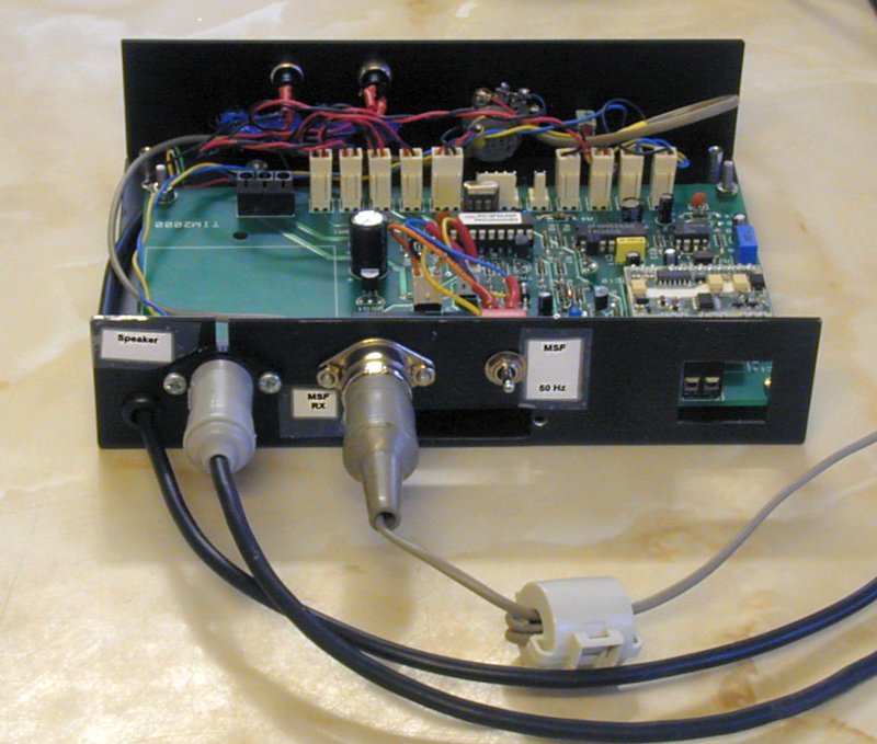
From left to right: power inlet for 12v AC supply, speaker oulet using a standard DIN socket, MSF receiver input using a 3-pin DIN connector, synch switch to choose either mains or MSF source of synchronisation, and telephone interface (through cut-out in case). The synch switch is done by extending the links from the middle of the board to a DPDT switch. Switching to MSF and unplugging the receiver causes the clock to run off its own internal crystal oscillator.
You can see that I've fitted a ferrite ring on the lead to the MSF module. I don't know whether it makes any difference, but it seems like a sensible precaution.
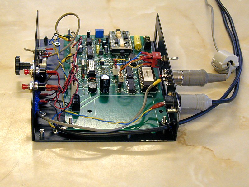
Just visible at the right is the P-type cable grip to prevent the power cord from pulling out. The modem case didn't have fixing holes in the same places as the speaking clock board. So I've used long countersunk M3 bolts with tubular spacers to support the board. Also just visible to the left is the ground connection from the case to the zero volts rail via a solder tag.
The LEDs are held in with RTV compound (Holts Instant Gasket actually). The connections to the links in the middle are made with some old Molex connectors out of an old telly.
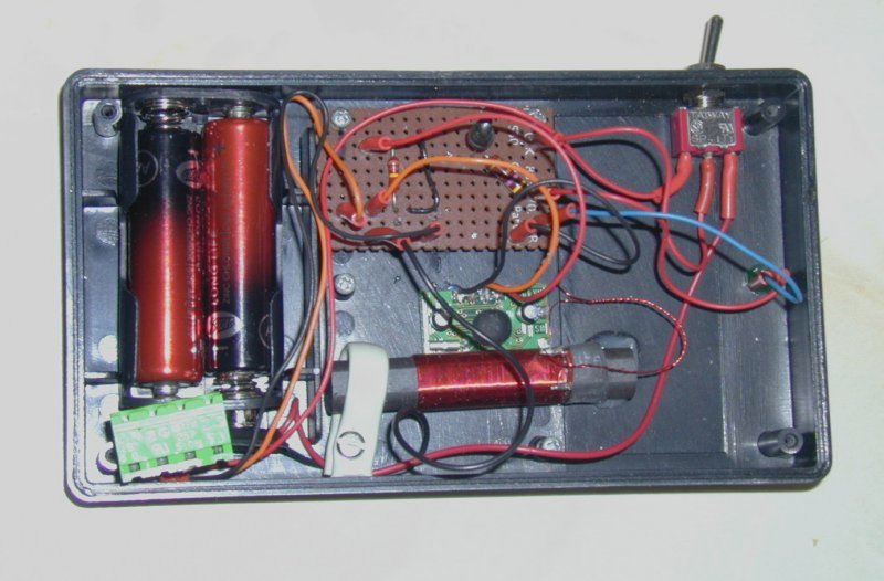
The MSF module is a bit messy inside, as it's a left-over from a previous project. The module itself is the small board in the centre with a black blob in the middle. It's fixed down with RTV compound. The antenna is held down with a piece of cable sheath on the left and RTV compound at the right.
In stand-alone mode it runs from the battery in the compartment on the left. With the switch (top right) in the off position, the +5 from the speaking clock is fed to the circuitry via the green connector below the battery.
The circuit board, top centre, contains an emitter follower to drive the LED (centre right). I have since changed this arrangement to a 4069 hex inverter to act as a buffer/ line driver. See below.
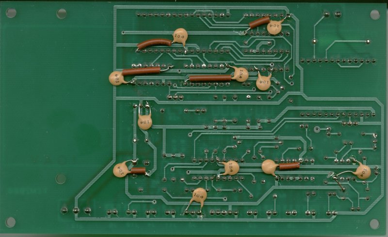
Brian McGennity e-mailed the THG mailing list to recommend some modifications to improve the noise performance of the speaking clock. He advised fitting 100 nF capacitors across the power feeds to each chip. This picture shows them fitted to my board. Interestingly the picture was taken by placing the circuit board on a flat bed scanner.
More information on mods at
https://britishtelephones.com/andyemmerson/tel_info_tim2000.html#User%20feedback
Item 16
Other mods that I finally added in 2006 are:
For details of my interface see Interface page
Here are some useful links about the speaking clock and its history.
Speaking Clocks An article from Bob Freshwater's site with the history and photographs.
The BT Speaking Clock Mike Fletcher's page of history with pictures of Brian Cobby and guest voices, Lenny Henry and Alicia Roland.
Original page 2001, Modified 2022, 2026 (with Lightbox)
Photos: © Sam Hallas 2001