
Sam Hallas' Website

Following on from the success of TIM2000, the late Andy Emmerson, former President of the Telecommunications Heritage Group, asked the members whether a new version of the speaking clock should be commissioned. There was a positive response and suggestions were received on how the new clock should work with many more options specified.
Once the specification was firm, Andy handed the development work to Unusual Electronics, who have expertise in real-time clock applications. The resulting prototype was produced in 2015, hence the name.
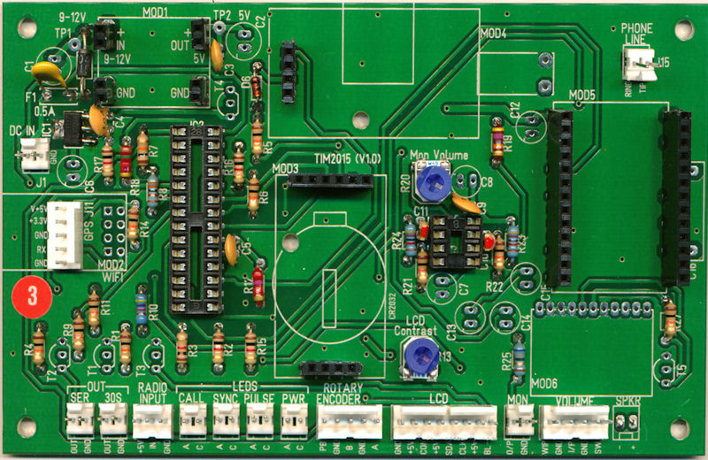
The prototype proved successful and the time keeping was exceedingly accurate so professionally produced circuit boards were manufactured. The boards are double-sided, silk-screen printed with plated-through holes.
The pictures are all clickable for a larger view. Use ESC to return or click the X button.
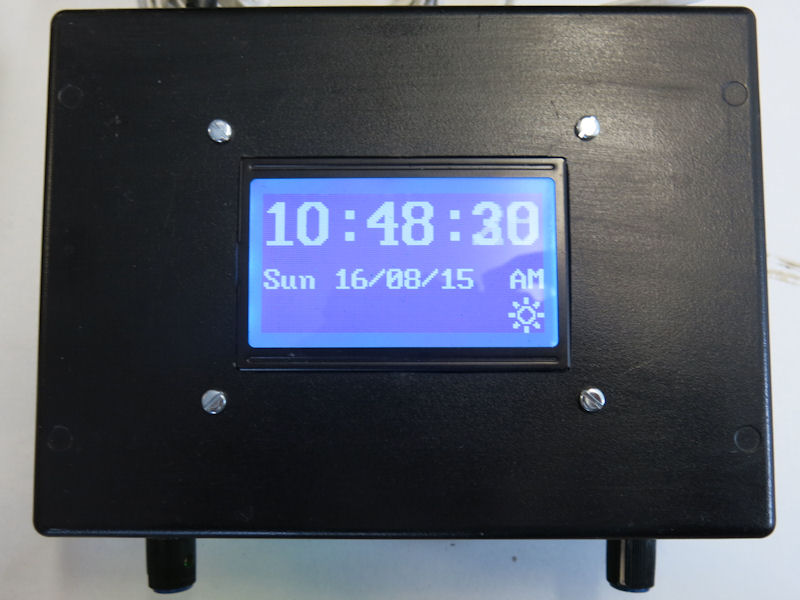

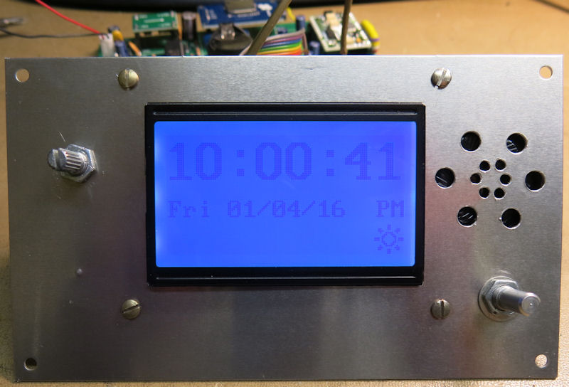
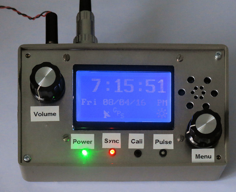
TIM 2015 has an LED screen display which shows the time and date.
The front panel contains the menu function selector (left), the volume control (right), loudspeaker and status LEDs.
TIM 2015 was offered in two forms. One was a complete, assembled model which only required a power supply and synchronisation source to be added. The other was a self assembly kit comprising a bare circuit board with the pre-programmed PIC processor, the custom Mitel telephone interface and engraved front and back panels. A micro-SD memory card was supplied with each type containing the recordings of Pat Simmons' time announcements.
The self-assembly kit required the purchaser to source all the remaining parts themselves. An assembly manual was provided.
I'm going to describe the processes I went through to build my TIM2015.
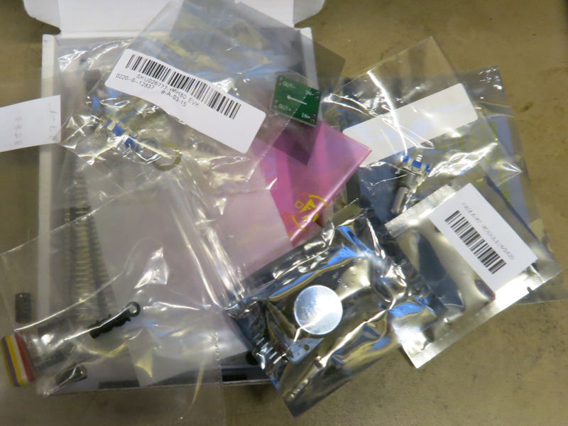
TIM 2015 uses a number of pre-assembled modules. Most of these were sourced from UK suppliers and many are advertised as being suitable to use with Arduino or Raspberry Pi processors.
I've put together a file showing the major parts and, as appropriate, where I sourced them. TIM2015 Parts & Modules
I was able to find a number of the small passive components in my spares boxes. The majority of the remainder I ordered from Farnell Components. There was sufficient to qualify for free postage.
Some items that weren't in stock, and some others that I forgot earlier, I ordered from RS Components.
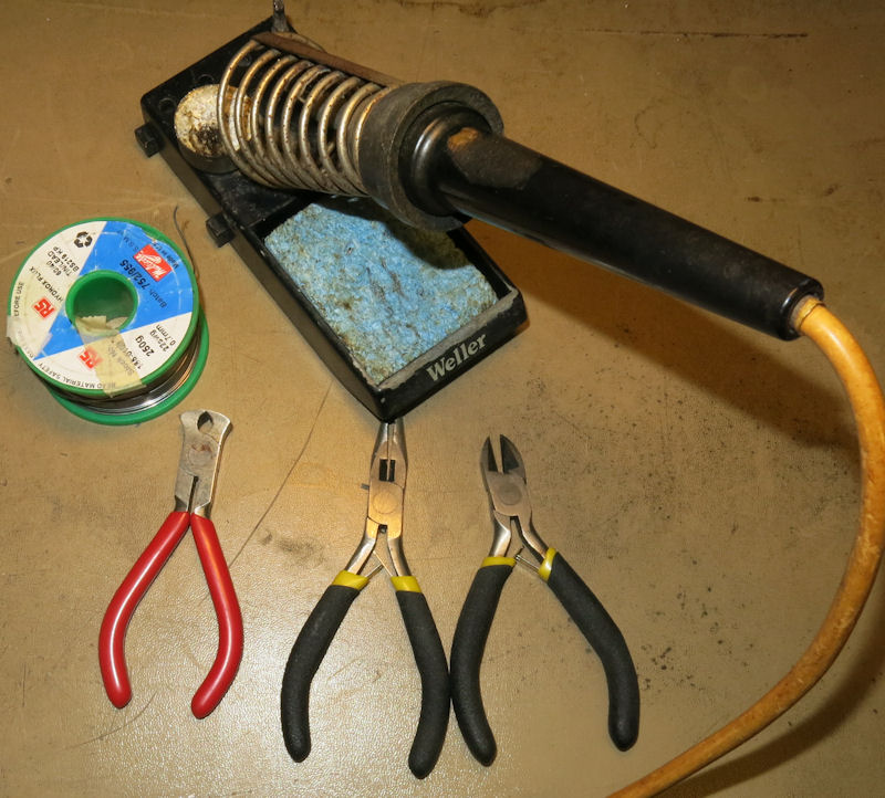
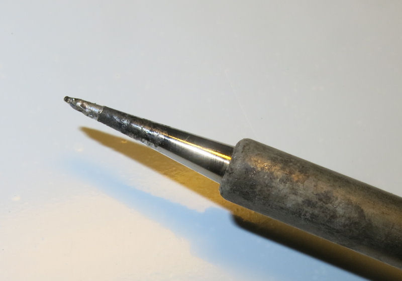
Populating the circuit board only needs a few tools. It's worth while using a temperature controlled soldering iron. I've had this old Weller iron for many years. Bought at an amateur radio swapmeet, it's been a sound investment and a boon for all my projects. However, I treated it to a brand new fine tip (right) for this job. The solder is 22 swg which is better for this fine work than the usual standard thickness. It isn't lead-free since I've had it for ages and only use a small amount per year. There'll still be plenty left in 10 years' time.
The end nippers are the best tool for cropping the component wire ends.
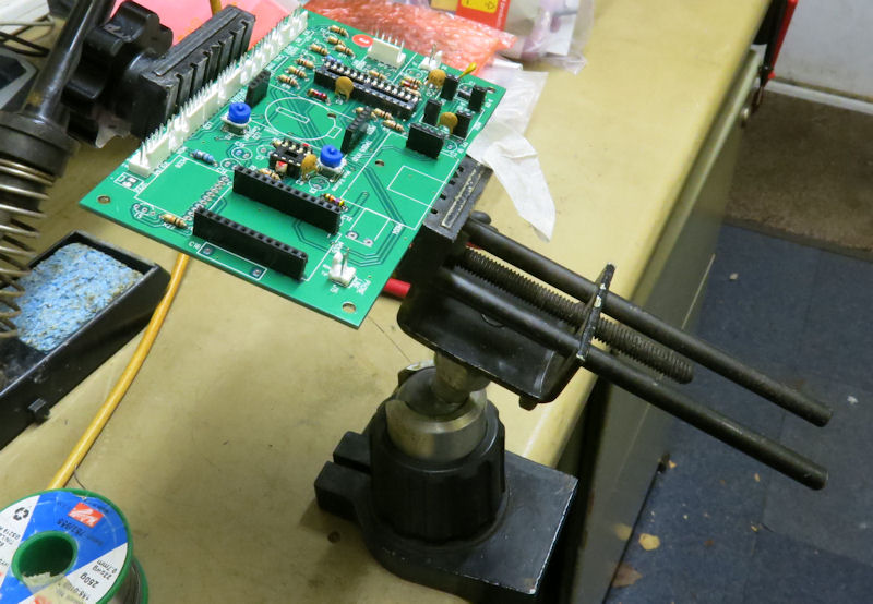
A most useful piece of kit is this swivel vice (below) with wide jaws designed to hold circuit boards for populating and soldering. I think it was a cast-off from work. If, like me, your eyesight is losing accommodation for close work, then clip-on specs that can be flipped up to restore normal vision will be a great help. (What an awful selfie!)

To help me during the fitting of components I rewrote the parts list sorted by type. This puts all the same value components together, making it less likely that I'd miss some. The list can be downloaded here. Small Parts list
I find it most frustrating when I fit components to a circuit board. They sit nice and flat against the board until you turn it over for soldering. Then they either drop out entirely or slip to an ungainly angle. I got round this problem by holding parts in place with sticky tape. Masking tape has the right sort of stickiness - not very sticky. I used Micropore surgical tape because I had some in my workshop. The picture shows the group of resistors bottom left of the board held in place prior to soldering.
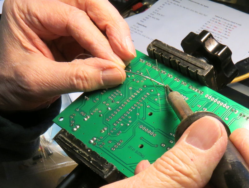
Then it's just a matter of soldering the parts in a few at a time and cropping the leads. The instructions, wisely, tell you to fit the low rise parts first. This is very practical as the taller components would get in the way if you put them in first. You'll find, as I did, that soldering to points that are on the ground plane take a while to heat up as the copper plane acts as a heat sink. I'm not sure whether it's worth while holding the soldering iron on a joint for slightly longer than normal to allow the solder to wick its way through the plated holes.
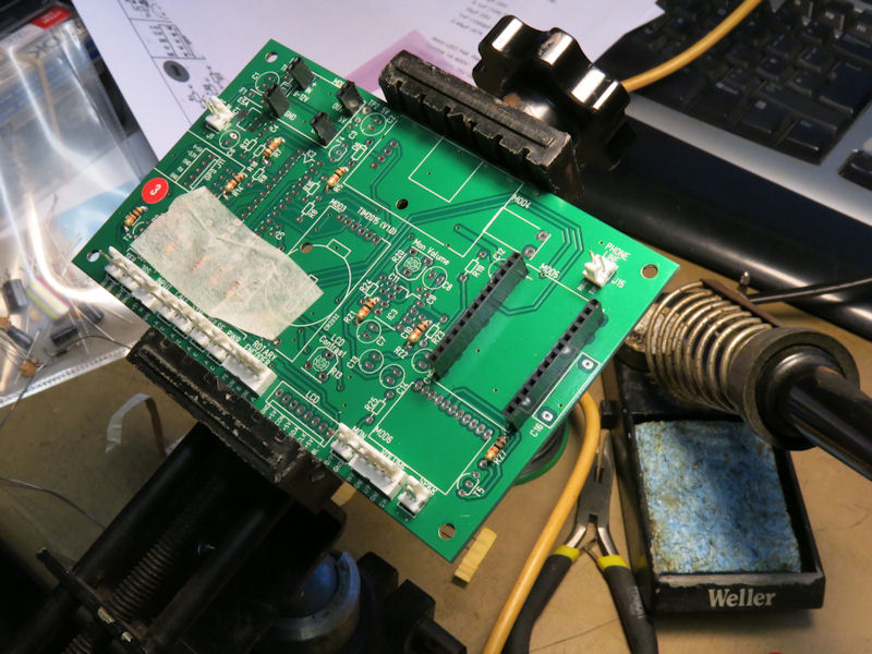
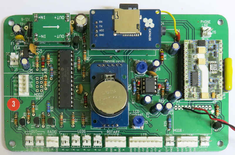
This is what the board looked like at about Page 11 in the instructions (below). You'll notice that I've fitted the row of Molex connectors at the front backwards. This is my preference as I think they should face outwards for convenience. As long as the matching socket is wired right, it doesn't really matter. Notice also that I've chosen to socket all the modules that I can. It makes troubleshooting easier. I know how difficult it is to unsolder from double-sided boards. (I'll explain why I removed the Molex connector for the speaker later, and also why I replaced it)
The final result showing the board fully populated with small components can be seen in the small parts list file.
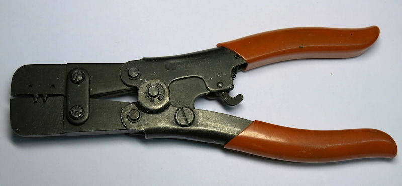
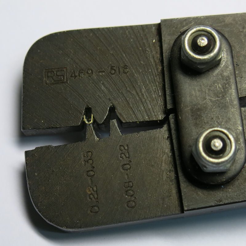
On previous projects I've terminated Molex crimp pins by squashing them in a pair of pliers and, usually, soldering to complete the job. I discovered that before I retired I managed to acquire the proper tool that was surplus to work's requirements. (left)
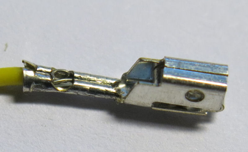
It took a few botched attempts before I found the best way to use the tool. Hold the crimp pin in the larger V-shaped notch and gently squeeze the tool handles until it's gripped. (see picture right, top) Insert the pre-stripped wire with a small amount of insulation into the end of the crimp. Squeeze the tool fully until the handles release and dislodge the crimp pin. A good crimp looks like the one on the right, below the tool.
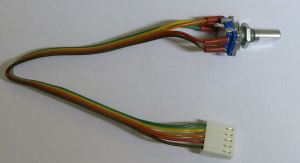
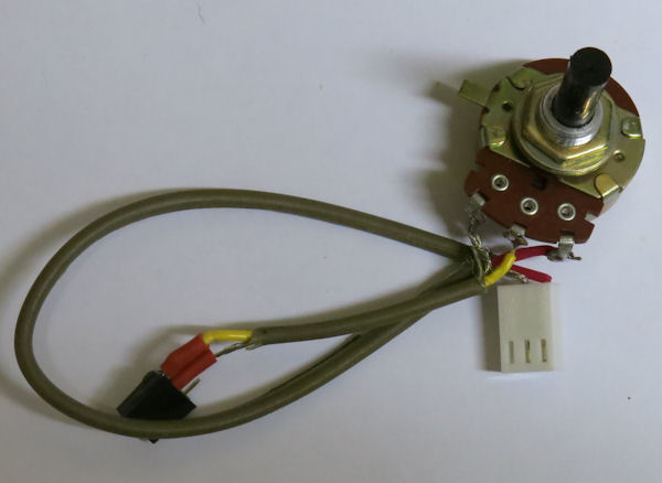
To make the twisted leads I used the age-old method of pinching the lengths of flexible wire in a vice at one end and trapping the other end in a drill chuck. Turn the drill gently until the required degree of twist is obtained. For the two items with larger connectors I used some of my stock of multi-coloured ribbon cable. As you see below the wires are coloured according to the resistor colour code - Brown (1), Red (2), Orange (3), Yellow (4) etc. - making it easy to get the order right.
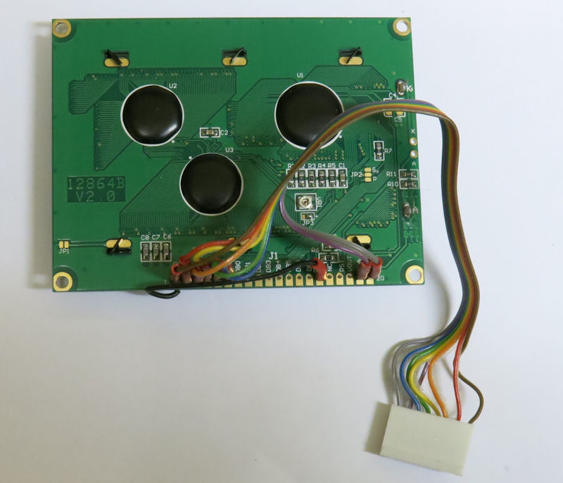
Here are some of the peripherals with their leads fitted to the Molex connectors. The LEDs are marked with their colour and function as the colours can't be seen until they're operated. Maplin didn't do a yellow LED in the range I chose, so the 'Synch' lamp is orange instead. The volume control is an un-switched type so I've only connected the audio input with screened cable. I fitted the LCD display with short lengths of header to make termination easier. You can see I put a jumper from the PSB connection round to the back of the ground connection on pin 1. This is to enable serial mode.

The Molex connectors proved to be the most troublesome part of the project. Wires kept snapping off just where they joined the crimp pin. With care the pins can be pushed out by pressing the retaining lug down with a small screwdriver whilst pushing up the socket hole with a narrow prod. In order not to waste the pins, I stripped the wires and soldered them on before pushing the crimp pins back.
Two important things to be done before the modules could be inserted into their sockets.
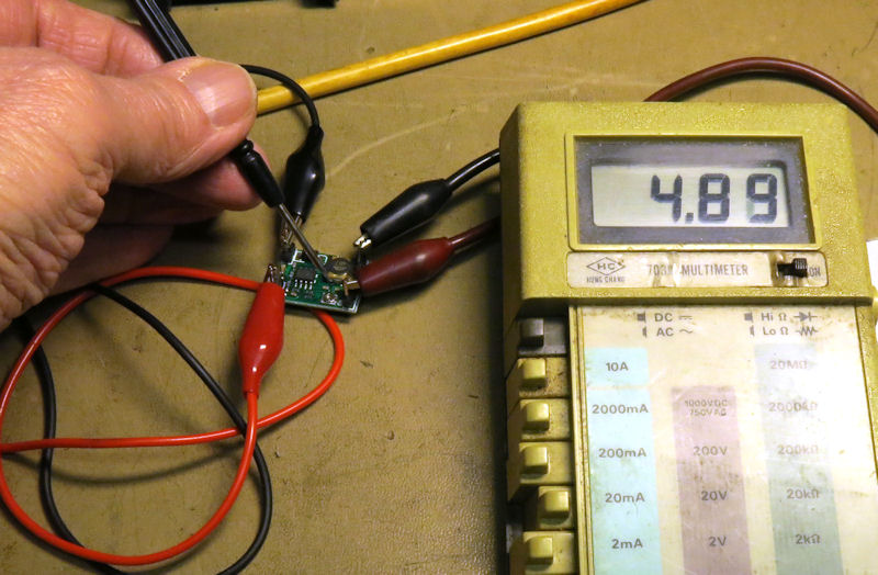
First the voltage regulator needed to be set to the right output voltage. See the TIM2015 assembly instructions for details. I used a jeweller's screwdriver to adjust the variable resistor. It proved a bit tricky to set, but I got it to an adequate setting just below 5 volts. (left)
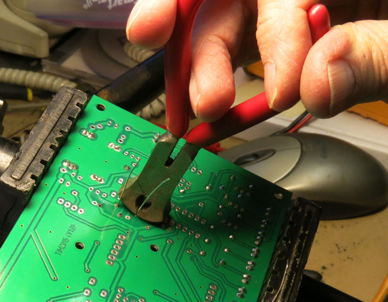
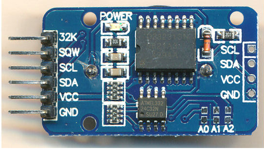
The other one was to remove the diode on the real-time clock module as in the instructions. It's the orange tubular device to the right of the main chip. (right) I warmed it gently with the soldering iron at one end and lifted the end up before warming the other end to remove it completely. The connector pins had to be bent at right angles to the board and a header fitted to the other end to give a firmer mount.
The same service of pin bending needed to be done for the Catalex MP3 player module. The audio output needed to be connected to the main board. I fitted a Veropin to make it easier.
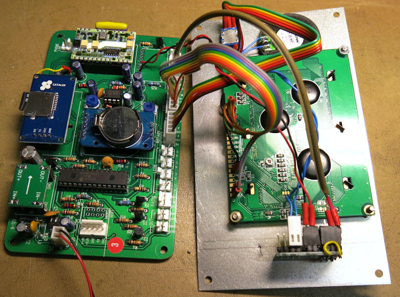
Here's a view of the completed board. Notice a few things. I've rounded off the corners as part of my plan to put it in a different case from the one specified. The PAM amplifier module is not present as I was going to mount it on the front panel next to the volume control. For that reason there is a flying red and black lead with ground and 5 volts leading to power the amplifier, also to go on the front panel.
At that stage I plugged a pair of headphones into the Catalex module, inserted the SD card, connected all the LEDs and the LCD display and applied power to the unit. The LCD showed the TIM 2015 logo and requested the time to be set. However the backlight in the LCD was not on. As I moved the LCD display the backlight came on. It didn't take too much deduction to figure out that the 5 volt supply to the backlight had an intermittent connection. As I went to disconnect the LCD module the violet wire fell off the Molex connector as it had snapped off, just like I complained about earlier.
Once the LCD violet lead had been repaired the backlight functioned correctly. Pressing the rotary encoder shaft caused the settings menu to appear. I had to turn the shaft anti-clockwise to step through the menu functions. The assembly instructions didn't give details of the encoder connections so it was pot luck which way round they went. I guessed wrong. The picture above in the Molex section shows the corrected version.
Once the time and date were set, the unit started making time announcements. I confirmed that it retained the time settings with the power disconnected.
There was a slight panic moment on a subsequent reconnection of power. There was an error message about the real-time clock module. I tried taking its battery out and putting it back. Unlike most other occasions where turning the power off and on makes no difference, in this case it restored function to the clock.
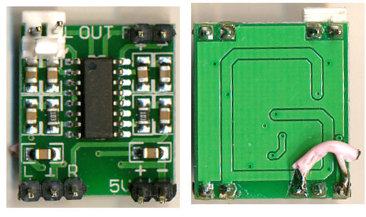
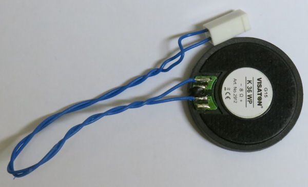
The item missing up to now was the PAM amplifier module. Here it is on the left, fitted with headers for the power and audio input and a Molex connector for the loudspeaker. I joined the left and right channel together underneath. The pesky solid-core wire had insulation that shrank back as soon as the soldering iron heated the wire. The right hand channel may come in later for an external speaker. This is also where the 2-pin Molex header went to earlier. The eagle-eyed among you may have spotted that in the finished board, the speaker output connector has reappeared. This is because I remembered that I ordered an extra one for just such an eventuality so I reinstated it.
Now that the main board was proved to be working I could connect the amplifier module and the 1½ inch loudspeaker up to the volume control and power lead. The sound seemed rather quiet, but I found that the loudspeaker produced much more sound if it was placed over a cavity, such as the roll of sticky tape or the solder reel.
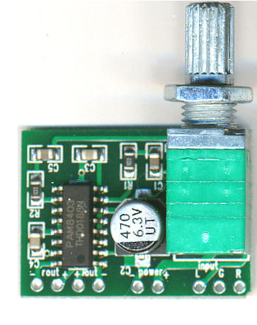
It was about this point that I discovered an alternative amplifier board which had a volume control with switch attached (above right). This would make the whole thing much easier to mount. However, as we'll see later, there was a penalty to pay in terms of clearance. I ordered one through Amazon and while I waited got on with testing and preparing the case.

The case I decided to use is a sloping front design which will allow the display and controls to be on one surface. It's a tight fit as you can see above. I had to round off the corners of the board to avoid fouling the cover mounting pillars. It also looked as if the loudspeaker would have to fit on one side, but this turned out not to be necessary. There isn't a lot of overhead clearance for the circuit board which is why I went originally for a volume control without a switch. The critical items to be kept clear were the power regulator top left and the telephone interface top right.
I drilled two holes for M3 countersunk screws to fix the circuit board at its base. I fitted short spacers to lift the board clear of the case and let it rest on the case at its top edge.
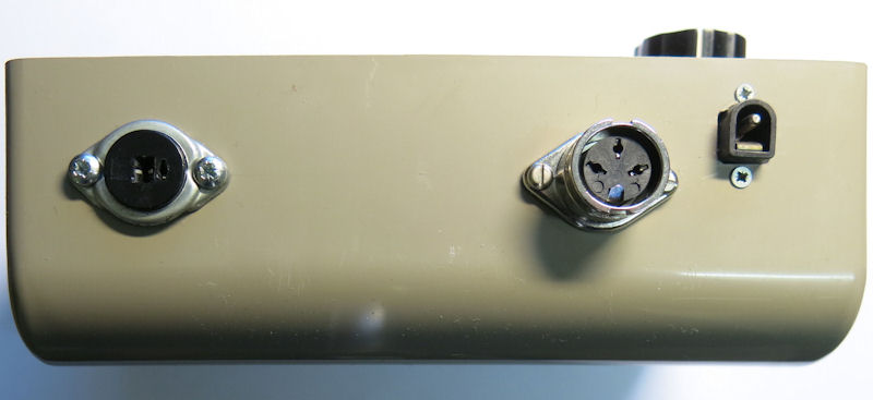
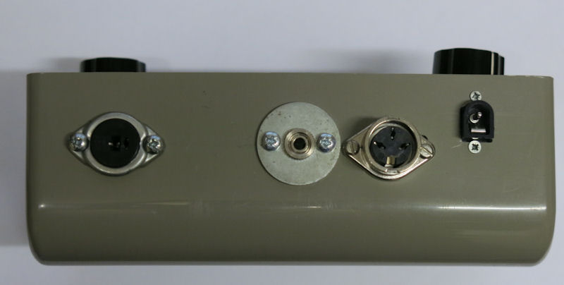
I decided to use a DIN speaker socket for an extension loudspeaker and a locking 3-pin DIN for the external synchronisation signal. These required 25mm holes which I cut with a hole saw I've had for many years. They're mounted slightly too low, making the clearance over the Catalex module a bit tight.
The power inlet is a 5.5mm standard type from Maplin. It's hole is a bit of a mess, made by elongating a round hole with a flat file. It's fixing screws are M2, which are very fiddly. It's also mounted a bit too high as I found later when fitting the lid.
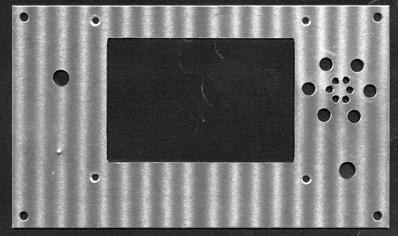
I marked out the front panel to mount the LCD display centrally and as high as possible, avoiding fouling the lip of the case. I would normally have drilled a hole large enough to admit a jigsaw blade and cut out the rectangle from there. However, a friend with a milling machine offered to do the cutting for me and made a better job than I would have done. (The stripes in the picture are an interference pattern from the flat bed scanner lamp. The dimple lower left is an accidental centre punch mark for the volume control, but measured from the wrong edge!)
After a lot of careful juggling with the amplifier module and the rotary encoder I decided on their placing to avoid hitting the components below. This explains the rather lopsided layout. I would have preferred the amplifier and volume control to be on the right, near the Molex connectors and speaker socket, but the size of the underlying telephone interface prevented it. The volume control position ended up slightly too far to the left. It's supposed to be clear of the GPS Molex connector with the knob clear of the LCD display. Sadly it hits the connector when the Molex plug is inserted. I want to use the GPS input to provide synchronisation, so I ordered a set of right-angle header pins to replace the Molex connector which will solve that problem.
I've made a template that can be used as a basis for cutting and drilling. Drilling template, with suitable changes to avoid my mistakes.
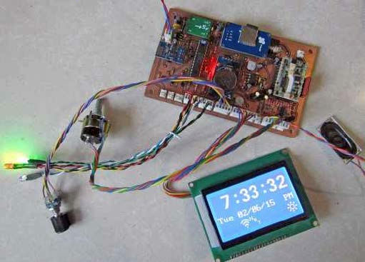
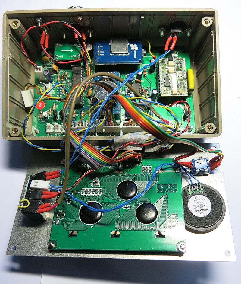
The picture above left shows the board and front panel coupled together for bench testing and above right shows the display in operation. The LED indicators were drilled out later, on 20mm centres below the LCD display. The loudspeaker has been trapped underneath the edge of the LCD display circuit board, thus solving the problem of how to fix it. Below is the completed assembly ready for the lid to be closed (except I just noticed that some nuts are missing). I know it looks a bit of a rat's nest, but the cables are long enough to allow it to be serviced on the bench easily.
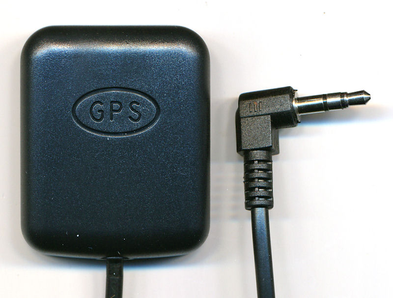
Unusual Electronics have a design on their web site for a GPS time display which uses a cheap GPS receiver intended for use with certain vehicle dashboard cameras. On the assumption that this was the correct one to use with TIM 2015 I ordered one from the eBay supplier shown in the parts & modules file.
A soon as it arrived I set about testing it. The GPS Molex connector was already wired out to the 3-pin locking DIN socket on the back of the case, so it was a matter of adapting it to the stereo 3.5mm jack plug on the unit. I already knew that there was good GPS reception in my shed/ workshop. Using my mobile phone and AndroiTS GPS Test I can always see at least eight satellites with the phone on the work bench.
As a result the 3-pin locking DIN socket on the TIM case reverted back to connecting the radio module. The 3.5mm stereo jack has been mounted alongside to connect the GPS module. The jack is designed to mount on thin metal and not the thick ABS of the plastic case so it had to be fitted to a large washer drilled with 3mm holes in order to fix it.
I was gratified to see that the GPS module was working straight away. I set the Time Source to be GPS and immediately the blue 'Pulse' light began to flash. After several minutes the orange 'Synch' light came on and the 'Pulse' light went off. I checked the time announcement against the MSF-linked wall clock and confirmed that TIM was in synchronism with it. I turned the menu knob two notches and checked that the display showed the date and time of last synchronisation correctly. A quick voltmeter reading showed that the GPS module was now powered down as described in the manual.
Up to this point I'd been testing the TIM2015 using a pack of three Lithium-ion batteries which produce about 11.1 volts. As I have a 5 volt mains supply, surplus from an old Virgin media set top box, I toyed with the idea of disconnecting the 5v regulator and feeding straight in at 5 volts. Or maybe using a USB power lead? However in the meantime I found an old 12 volt supply so I could leave TIM on overnight to see if it re-synchronised in the night as claimed in the manual. And it did - at 05:20.
Once the right-angle header pins arrived I was able to replace the GPS Molex connector on the circuit board. The Molex plug still fitted, although it had to go the other way up, which meant re-ordering the pins. Finally I could screw the lid on.
I unearthed my Dymo label machine and made some labels for the controls and lamps and took a final series of photos of the clock in full working mode. This is a composite of two shots, since the contrast between the screen and the rest of the picture is too high.
With both TIM 2000 and TIM 2015 switched on, it was gratifying the hear the pips sounding in synchronism.
I've just heard that the silk screen labelling of resistors R22 and R23 is transposed so I've put the resistors in wrong way round. This doesn't stop it working but changes the bias on the two halves of operational amplifier, IC3, and makes the gain of the main audio path too low. I'll decide later whether I'm going to swap the resistors back.
Dave Thorpe, the designer at Unusual Electronics has found an anomaly in the transmission from radio MSF that was confusing his error checking routines. He's made some changes to eliminate the clash and has issued an updated version of the firmware. Andy Emmerson will arrange to swap out the PIC processors if you have Mark 1 firmware .
I think I've also spotted another resistor swap. R17 and R18 appear to be wrong way round. The values are very similar - 1.5k and 1k - and only affect the WiFi interface.
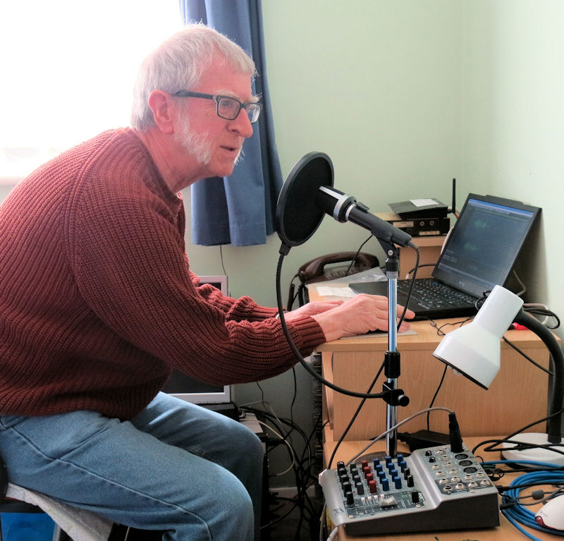
The ultimate ego trip is to have your own voice making the announcements. So to that end I set up my voice-over kit in the spare bedroom and started recording.
I record using an AKG dynamic microphone fed into Peavey PV6 mixer with USB interface into a Dell laptop. The pop screen has the advantage of reducing room reverberation as well as suppressing voice popping. The computer is running an early version of Adobe Audition that I bought many years ago when it was comparatively cheap.
The file arrangements are shown in the User Manual, although the opening announcement and the hours are now concatenated. The first items I recorded were the preamble and the hours. I wanted the preamble to be like the later Brian Cobby announcements and go, "At the third stroke the time will be…" I followed that with the numbers from one to twelve. After an editing session I had the 24 files all normalised to maximum volume. The twelve "At the third stroke the time will be one…" etcetera formed files 001.wav to 012wav. The twelve numbers were saved in files 101 to 112.
Then came the slog of reciting the numbers from 13 to 59 for the remainder of the minute announcements. I did that in one long take and then edited and normalised them for files 113 to 159 along with file 100, which says, "O'clock." Finally I recorded the seconds announcements, "... and ten seconds," etc to "precisely". for files 200.wav to 250.wav.
I took great care (so I thought) to make the sound files as much like the working Pat Simmons files as possible. The preambles were exactly three seconds, the numbers exactly one second and the seconds exactly two seconds. My files were all created as stereo .WAV files, though both channels were identical. I converted a few to mono, but it didn't seem to make any difference, apart from being slightly smaller files. The Catalex module will also play .MP3 files, but apart from the smaller size there isn't any advantage in compressing them to MP3 apart from making them easier to download.
I created a fresh SD card with the existing voices and added my own as Voice 5, plugged it in and switched on.
The first thing I heard was, as usual, the pips, then the announcement, "At the third stroke the time will be one, twelve and twenty seconds." But instead of the pips I got the next announcement, "At the third stroke the time will be one, twelve and thirty seconds," followed by a long wait for the time display to catch up and finally the pips in time with seconds 28 to 30. Next I got, "one twelve and forty seconds," followed by an even longer pause. I retired, puzzled meaning to sort things out the next day.
After a good night's sleep I switched on and found that all the announcements had disappeared and I only got pips. So I started a diagnosis of the problem. I copied all the Pat Simmons preambles to replace mine and tried again. By setting the time source to 'None' I could change the time an hour at a time and check each preamble in turn. (I found later that the source could be left as it was for the purpose of this test) There were no failures, which sent me back to editing my sound files. A comparison with Pat Simmons showed that Pat had at least 0.5 seconds before the preamble start, whereas mine went straight in. By cutting some of the gaps in my speech I managed to make the first preamble start with a half second silence and fit the rest in the remaining 2.5 seconds. That seemed to cure the problem, so I went through and edited the other eleven files by cutting the gaps and inserting extra silence at the start. It didn't seem to matter if the files went a little over three seconds. However, see my later findings when TIM went 24 Hours. That seemed to cure the problem and TIM has been running for a couple of months now and the announcements are working well. Click the play icon to hear a sample.
If you would like to try the Sam Hallas voice files on your TIM 2015, you can download them in MP3 format as a zip file here. [2.0 MB]
I was chatting to Andy Emmerson at the Milton Keynes swapmeet in 2016 and wondered if it would be possible to alter the firmware to cope with 24-Hour announcements. Andy admitted that he had thought the same and he had commissioned Dave at Unusual Electronics to write the changes. In anticipation I prepared some sound files for "At the third stroke the time will be thirteen..." and so on up to twenty three. I did this by editing from existing sound clips but then needed to record "midnight", and for good measure "double-oh". After a bit more thought I recorded the numbers "oh-one" to "oh-nine" as well so I could try them out. I saved the new hours file as 000.wav (for midnight) up to 023.wav. I saved "double-oh" as file 100.wav to replace "o'clock", because "Thirteen o'clock" sounds a bit odd.
I sent the PIC chip off to Andy for reprogramming. On its return I loaded a new folder with the 24-hour voice files and replaced the SD card. After I had reconnected various wires that fell off due to poor original soldering and Molex disease, TIM sprang into life. It was after six o'clock in the evening but no sign of it being spoken as "Eighteen forty-seven and ten seconds". A quick exchange of emails with Andy discovered that Unusual Electroncs had set the midnight file to be 024.wav. This was because Dave at Unusual Electronics had tried the more logical 000.wav, but the Catalex sound module ignored it, so 024 it had to be. I hastily changed the file name, reloaded and, bingo, it was all speaking properly.
I listened to the clock say "…it will be midnight, double-oh" and next morning to "nine double-oh… ". I considered whether I should change "midnight" to "double-oh" and decided not to, but to change the hours from one to nine to be "oh-one" etc. A quick edit of the files and it was done.
It's just a pity the front panel display remains in 12-hour format. I gather it's a major rewrite of the firmware, so a further firmware modification seems unlikely.
I wrote the above in early 2018. Over a year later Andy Emmerson commisioned the necessary re-write to complement the selection of new overseas voices being collected and a fresh issue was created which now does display in 24Hr format when there are 24Hr voice files. Contact Andy direct if you want to update your unit.
After a day or so of running in 24 hour mode I noticed that the tail end of the "…and ten seconds" messages was being lost. I guessed that the "At the third stroke…" files were slightly too long. After a lot of messing around and comparing with the original Pat Simmons files, I decided to fix all of those files to be exactly 3 seconds long and reduce the opening silence accordingly. This seemed to work and I tested all twenty four of them with no truncation of the announcements.
You can download the 24-hour files here.
I noticed that the overnight time correction was seldom zero, mostly +1 or +2 seconds. I was able to check TIM against the time received from the GPS receiver in my mobile phone and found it was quite often slightly out during the day. Knowing that the radio time option corrects the time more frequently I decided to buy a receiver for the German standard time source, DCF which transmits on 77.5 kHz from Frankfurt am Main. Other TIM users have recommended DCF in preference to the UK source MSF from Anthorn in Cumbria which is more difficult to receive in southern England.
Andy Emmerson recommended a unit from PV Electronics . It comes complete with a ferite rod antenna. They can also supply one tuned to 60 kHz for MSF. Their price is reasonable and mine arrived next day. You can see from the pictures that the unit is exceedingly small. The fixing holes are only 2mm diameter. I thought about drilling them out to take M3 screws, but decided it might damage the circuit board. Instead I fitted mounting pins and plugged it into a piece of Verboard that I could screw down more easily. The socket is a cut-down IC socket from my spares drawers. I fitted pins to the antenna connection and a Molex connector to the antenna lead.
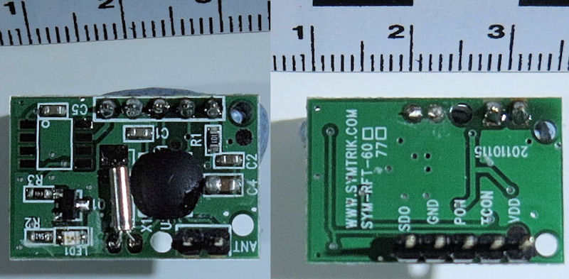


DCF Receiver, top and bottom view, antenna and mounting on Veroboard.

The DCF module contains an LED indicator to show when it's receiving a signal. This is very helpful when aligning the receiver, so it needs to be in a box with a transparent lid. Andy Emmerson has used a totally transparent box in blue polycarbonate from Hammond (eBay item No 131965595014), but it's rather expensive. I found a Waterproof Junction Box with a clear lid by SODIAL on Amazon, which is cheaper, though it comes from China and takes a while to come.
Once the box arrived I wasted no time in fitting the receiver module and antenna into it.
I thought I would replace the MSF receiver I use with my TIM 2000 and tried to source the Symtrik unit mentioned above. PV Electronics only showed the DCF module and it was 'sold out'. The only other suitable unit I found it is from Canaduino and is available on Amazon or eBay, but needs overseas postage rate, making it rather more expensive.
Ross Herbert as written from Australia to say he's designed some circuitry to provide standby power to TIM 2015 using a 3.7V Li-ion cell and charger and voltage boost modules. Sorry I haven't got round tofollowing this up. However, I've had success using powerbank to power items and as TIM requires a 5V supply this would be a good alternative.
Updated September 201, March 2018, December 2019, January 2026
Telecomms Index
Photos & text: © Sam Hallas 2016-7