
Sam Hallas' Website
Because the physical constructions are so different I'm going to do this bit separately. First the easy one, the printed circuit version.
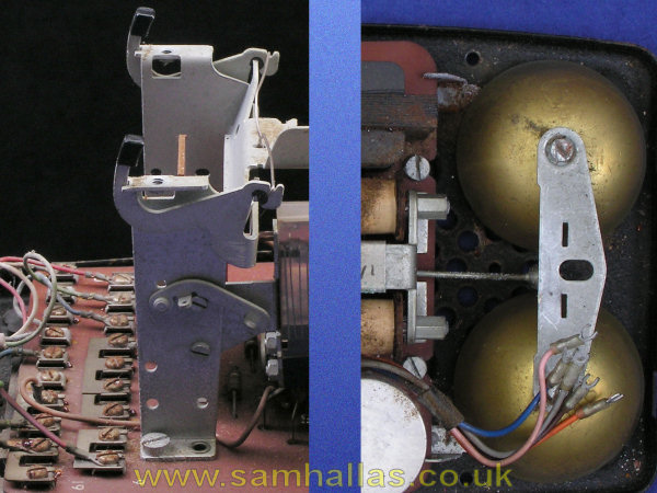
Four cheese-headed screws hold the circuit board in place. Two captive 3BA screws either side of the steel bracket (on the left) and two 4BA screws towards the front behind the bell. The front ones only need to be loosened to release the circuit board. Similarly the bell gongs and dial mount can be taken off, by removing the 4BA screws, leaving the steel base as seen on the right. Notice the plastic support for the circuit board at the back. This prevents the board cracking under pressure from screwdrivers when the terminals are being tightened. Two other plastic pegs further forward provide support.
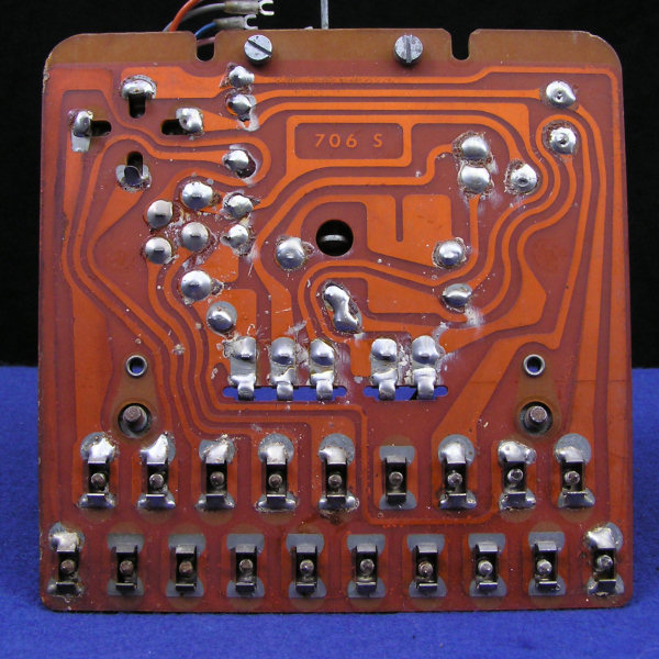
The circuit board is made from synthetic resin bonded paper, SRPBP, which was the natural choice for the time. Fibre glass boards were unusual and expensive at this time as well as being unnecessary for this application. The soldering appears to be done by hand, although very neatly. The board has lacquer coating over the track with only the solder lands exposed making it suitable for flow soldering. Terminals 11 to 18 are not soldered whereas they would have been if the board had been through a flow solder bath. The white deposits are the remains of resin flux as a result of age and dampness.
There's not much to clean on the circuit board. I brushed the terminals with a brass wire brush which took off a lot of the rust visible in earlier pictures. I rubbed the bell clapper with abrasive to smooth off the corrosion. The base had a similar brushing. Repainting didn't seem to be justified in my mind.
This telephone is a Mark 2A, as we saw earlier. This means that the bell is soldered in place. The earlier Mark 2 had the same bell as the wired version with a wire link between the two coils.
The wired version is more of a problem because it appears to be actually assembled on the base. The components cannot be simply unscrewed or unclipped to clear the base for cleaning. The regulator jack contacts are hot moulded into the base and cannot be prised out without destroying the jack. Since the whole point of this article is to take the phone to bits I decided to bite the bullet and unsolder the parts to allow them to be removed. If your purpose is only to clean the base, then going so far is probably too drastic.
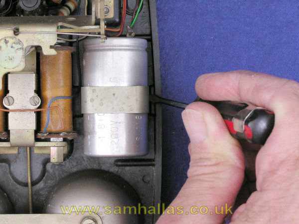
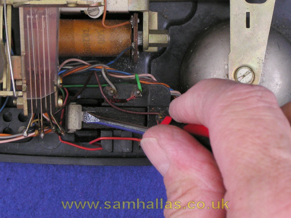
Firstly the capacitor can be unclipped by levering the retaining clip as shown. Similarly the transformer is clipped into place and can be released with a screwdriver. The cradle switch contacts simply unscrew. The bell unscrews from below.
Next, after taking a careful note of the wire colours, I unsoldered three wires from the transformer and one wire from the capacitor. Two other wires I cut to avoid damaging them where they were double soldered onto a tag.
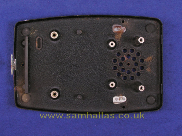
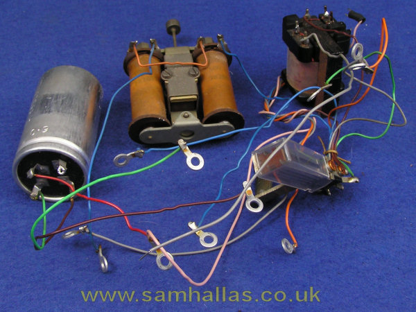
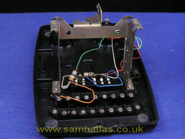
So, on the left are the parts I removed roughly in the same relative position they occupy in the phone. On the right is the base with what little remained that would not be damaged by washing. This picture was taken after washing with a pressure washer. On reassembly I reterminated the cut wires and the capacitor lead. The transformer wires slipped back on without bother.
I took the feet out of both phones. They come out very easily by pressing from the inside. However, they are pigs to get back. I can see no advantage in washing them separately so I advise you not to bother!
The bell gongs are mounted slightly eccentrically. When refitting them they should be turned so that the clapper just fails to touch them when stationary. Waggle the armature with your fingers to make sure that the clapper hits the gong and then falls back without damping the ring. The two gongs are tuned slightly differently to give that characteristic jangling ring. The wired telephone has Bell-gongs Number 23 and 23A, the printed circuit telephone has Bell-gongs 24 and 24A. I'm not sure why there is a difference. I have a wired Mark 1 from two years later which has Bell-gongs No 24 & 24A the same as the printed circuit Mark 2 here.
It was stated [Ref 1] that printed circuit techniques were quite novel in 1959 and some manufacturers preferred to stick with the traditional hand-wired construction. After taking the wired version apart and re-assembling it, I am surprised at this. The sheer simplicity of assembly of the printed circuit board must surely have made it quicker and cheaper to assemble.
The circuit diagram starts out from the incoming line in a similar way to earlier telephones. Magneto bell isolated by large value capacitor, C1A, which also forms part of the receiver circuit. Three winding hybrid transformer with balance components C1B and R2. Dial off-normal contacts, one which shorts the transmitter for improved pulsing and the other mutes the receiver to avoid clicks during dialling.
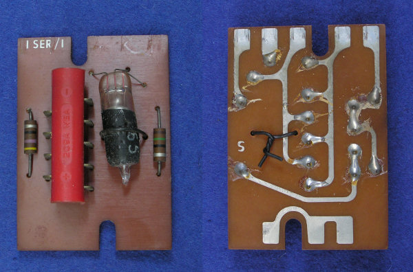
The innovation is on the left of the circuit diagram with the automatic sensitivity regulator, Regulator No 1. A detailed explanation is given in the POEEJ article [Ref 2]. Here is a simplistic description. The line current is passed through the resistor lamp (shown as a positive temperature coefficient resistor). This is the black painted glass bulb that looks like a lamp. As line current increases it provides an increasing potential difference across the back-to-back diode bridges - the red tubular item with nine leads. These diodes in turn partially shunt the receiver to reduce the sensitivity. At the time of design the public network was entirely Strowger based and current on short lines could reach 95 mA. Recent experiments [Ref 4] have shown that the regulator only provides a shunting effect at currents above 40 mA. On modern electronic exchanges where the line current is limited, it would have no effect.
Early regulators had clear glass lamps. Of course they glow a dull red as the line current passes through them. The story goes that nervous customers telephoning in the dark saw the phone glowing and dunked it in a bucket of water thinking it was on fire. Whether this is true or not, all later lamps were painted black.
The regulator can be reversed and as you can see from the circuit track layout, in that position it simply shorts out terminals B,C and D to maintain continuity. I don't know when it would be necessary to use the telephone in unregulated mode - maybe for local battery working.
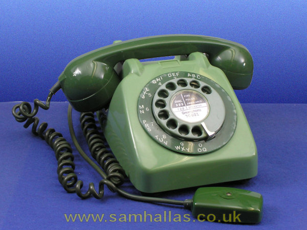
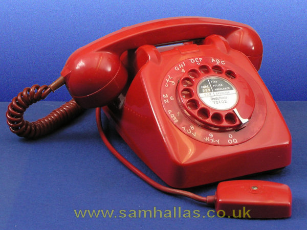
Here they are looking much better for a wash and brush up. Mr Green has a replacement Block Terminal as the old one was too heavily painted. Amazingly the paint came off the green cord with no problem after an overnight soak in soapy water. Mr Red has been fitted with a fresh BT too, since he came without one at all. The outer dial number ring on the red phone is in a poor state. As the red phone came without one and I picked up a loose spare, I should have chosen one more carefully.
Next we'll have a look at the new handset designed for the Telephone No 706, Handset No 3.
 Previous
Handset No 3
Previous
Handset No 3