
Sam Hallas' Website
This article is part of the Let's Take a Phone to Bits on the Telephone No 706 and is also included in the series " Handsets I Have Known".

Like the Telephone No 706 that it adorns, Handset No 3 was the first model using thermoplastic moulding on a standard GPO telephone. It was based on a design which had been field-trialled as Handset No 1 with modification to make it lighter.
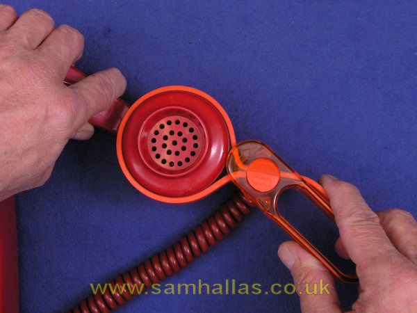
The receiver and transmitter caps unscrew from the main body. Their designations are Earpiece No 26A and Mouthpiece No 21A. The caps may have become stuck with age or just overtightened. There was a GPO tool to aid their removal which works much like the tool seen on the right. The one I'm using in the photo is a Baby Boa Constrictor which is sold as an aid for people with disabilities. It is a rubber strap attached to a handle which tightens the strap round whatever is being turned.

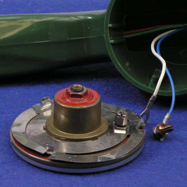
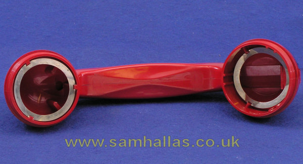
The two handsets I'm taking apart illustrate further changes. The green handset, left, has the earlier Transmitter Inset No 13. This is the familiar hat shape. Notice that it's been fitted with a screw terminal and nut to hold the spade connector on the handset cord. A special plug with thread and nut pushes into the rear connection hole. The three raised tabs on the transmitter fit into the recesses in the housing prevent it from turning.
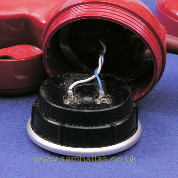
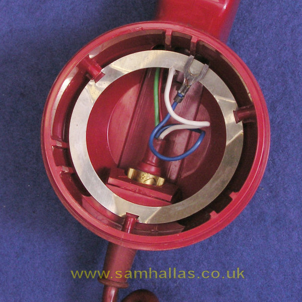
The red handset, right, has the later Transmitter Inset No 16 which has 6BA screw inserts ready to accept the spades. Inside the housing is a spring ring to press the transmitter firmly against the cap. The transmitter has ridges to engage with the same recesses to prevent it from turning. See below on the right.
Both type of transmitter use carbon granule technology.
Handset No 3 was designed from the outset with the upgrade of transmitter in mind. [Ref 8] The plastic moulding is cleverly designed to accommodate both old and new designs of transmitter.
Transmitter Inset No 13, the old hat-shaped variety had been in use for over 30 years by the time its replacement came along in 1965. In an earlier 'Take-a-Phone-to_Bits' on the Candlestick Tele 150, I noted that it was fitted with a Transmitter Inset No 13.
A great deal of design effort and testing went into producing the replacement transmitter [Ref 8]. Although increased sensitivity was not required, improvements were made to the frequency response and distortion, as well as mechanical improvement to the moisture seal and lower production cost. The POEEJ article in Ref 8 states that the design life of the transmitter was 2 years. This has proved to be unduly pessimistic. Many are still in working order at over 40 years old.
Transmitter Inset No 16 is not designed to be taken apart. It would be replaced entirely on failure. Total failure was comparatively rare, but degraded performance, such as frying and noise, were the main reasons for replacement. The transmitter was also prone to weak performance in severe frost when used outdoors in weatherproof telephones such as the Telephone No 745.

The Receiver Inset No 4T, although new to GPO mainstream telephone instruments had appeared already in the GEC and Ericsson 1000-Type Telephone and the GPO flameproof Telephone No 702.
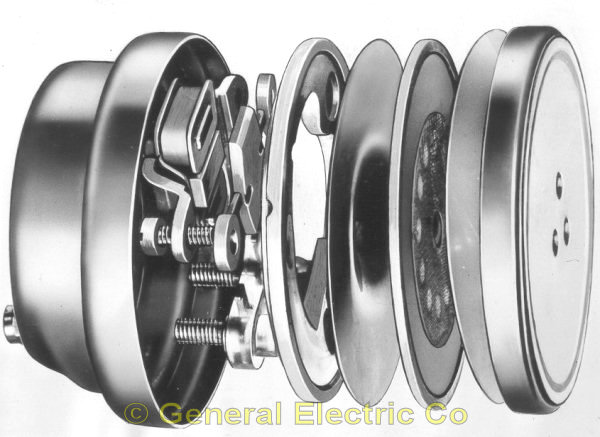
The 4T is described as a rocking armature receiver. An armature, rocking on a central support, drives a diaphragm via a small rod. The armature is polarised by a central permanent magnet and driven by two coils wired in opposition mounted either side. The whole unit is hermetically sealed.
The receiver is a great improvement over its predecessor, the Receiver Inset No 2P as used on the handset Tele No 164. Sensitivity is increased and the frequency response is smoother giving improved intelligibility. A fuller description of its operation is given in the GEC article about the 1000-Series telephone in the Document Repository. Like the transmitter, the receiver is sealed and not designed to be serviced. [exploded diagram: GEC, Bob Freshwater Collection]
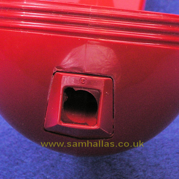

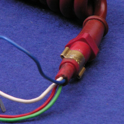
The handset cord is held in place by a crimped metal ring. If I show you the shape of the hole it fits in (left) you can see that the ring needs to be turned to allow it to slide out. I find that I can do this with a small spanner (right) or a small pair of pliers. Turn with the spanner at the same time as pulling on the cord grommet. There is a little arrow head on the inside of the moulded block to show where the ring must be turned to.
The picture on the left illustrates another point. In order to make the handset as light as possible, the handle is as thin as it can be made. This requires a largish core in the mould that is withdrawn through the grommet hole after moulding. The size of the hole required is too big for a grommet to sit snugly and so a small moulded block is glued into place which can be clearly seen on the left.
To refit the cord, thread the wires through the grommet hole, push the grommet into the recess and turn to allow it to slide in. The metal ring then springs round to lock the grommet in place.
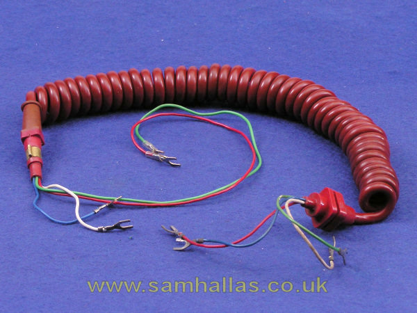
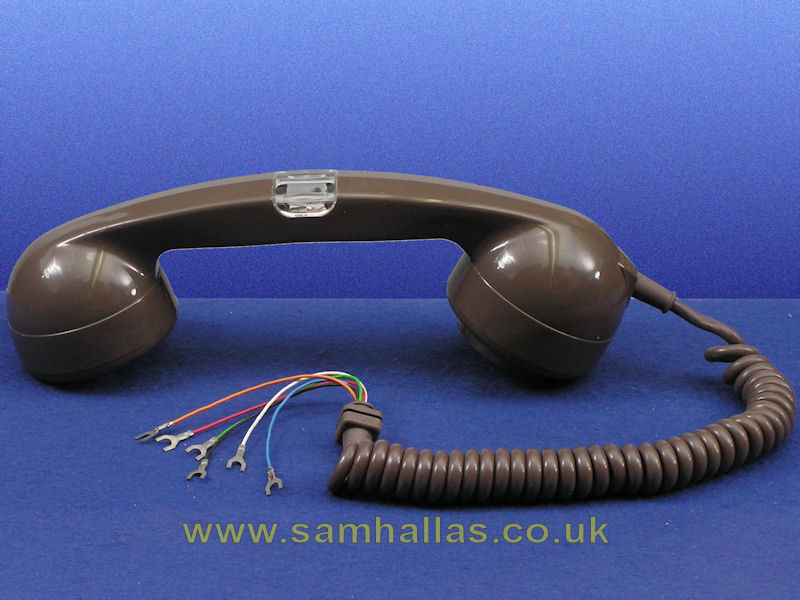
The curly handset cord was a first with the introduction of Telephone No 706 although some very early models had a fabric covered cord. The curly cord became available in 1959 in colours to match the telephone and handset body. The conductors inside are still of the tinsel type to give maxmimum flexibility. The new transmission circuit in the Telephone No 706 required a four-conductor handset cord (Cord Instrument 4/108) instead of the previous three-conductor cord.
Gone was the tie cord to retain the cord. In its place were moulded grommets glued to the cable itself. Gone were the fiddly wrapped loops for termination replaced by crimped spade tags. These are both plus points for reducing the cost of manufacture and actually make the cord easier to use.
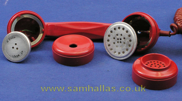
With the earpiece, mouthpiece, transmitter and receiver insets removed the plastic parts are ready for cleaning and reassembly. You can prise the spring rings out if you like, but they won't corrode from being washed and dried.
Handset No 3 spawned a number of variants for special purposes:
Handset No7
Continue to the Variants Page for more on the variant handsets, then return here.
The one-piece moulding of the Handset No 3 gives it exceptional strength. It is almost impossible to break the handle by bending the handset. It needs no screws or glue that a two-part moulding would require. However the one-piece construction makes it difficult to insert additional components such as the amplifier in Handsets No 4 and 5 or the lamp in Handset No 7.
Handset No 3 is much lighter than its predecessor, Telephone No 164. This is achieved at the expense of needing the extra block to be glued in the core exit hole.
The insets introduced with the Handset No 3 are improvements in transmission terms over their predecessors, Transmitter Inset No 13 and Receiver Inset No 2P, as well as being considerably lighter.
Handset No 3 was superseded by Handset No 16 used on Telephone No 776, the Ambassador and Stateman. Initially the insets were the same but in later telephones the carbon transmitter was replaced by a dynamic transducer.
Handset No 3 www.britishtelephones.com/hands3.htm
Similarly:
Handset No 4
Handset No 5
Handset No 6
Handset No 7
Handset No 14A
Handset No 17A
Earpiece No 26A and 29A
 Tele 706 Part 3
Tele 706 Continued
Tele 706 Part 3
Tele 706 Continued