
Sam Hallas' Website
This article is part of the Let's Take a Phone to Bits on the Telephone No 706 and is also included in the series " Handsets I Have Known".
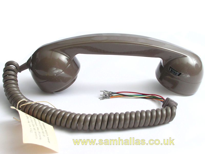
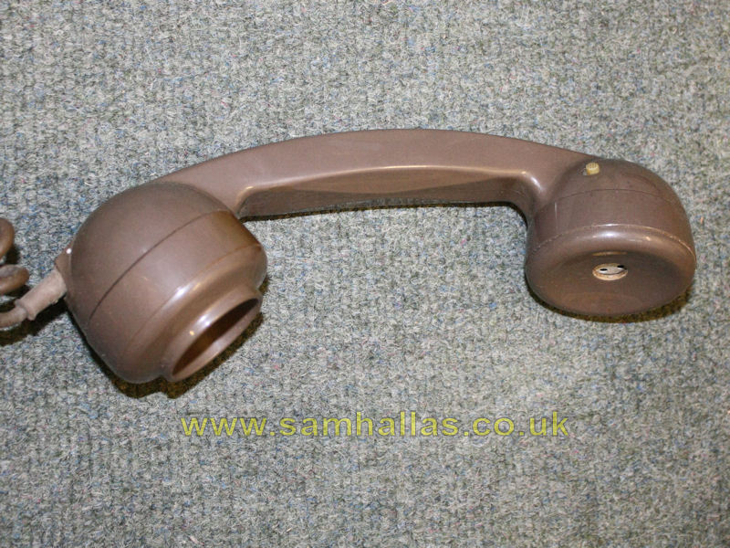
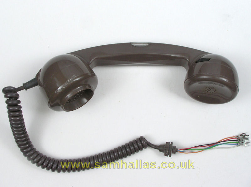
Handset No5
Handsets Nos 4 and 5 are designed to assist users with hearing difficulties by amplifying incomng speech using a single-transistor amplifier. The circuits are broadly similar with the No 4 being designed to run from telephone line current and the No 5 to run from a local battery. Diagrams N1840 and N1841 illustrate the difference.
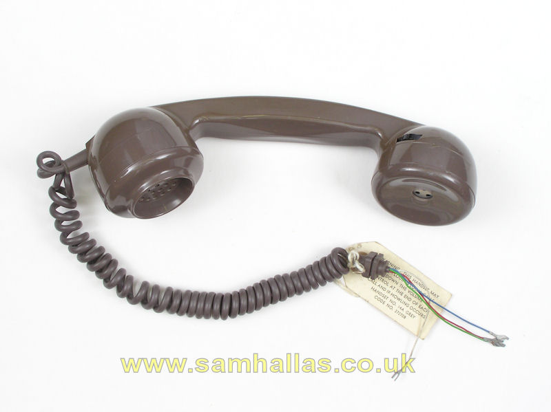
The handsets were issued separately for field replacement of an existing Handset No 3. The curly cord comes with a label warning, "This set has high amplification for very deaf users and 'howling' may sometimes occur. If this should happen, turn down volume control."
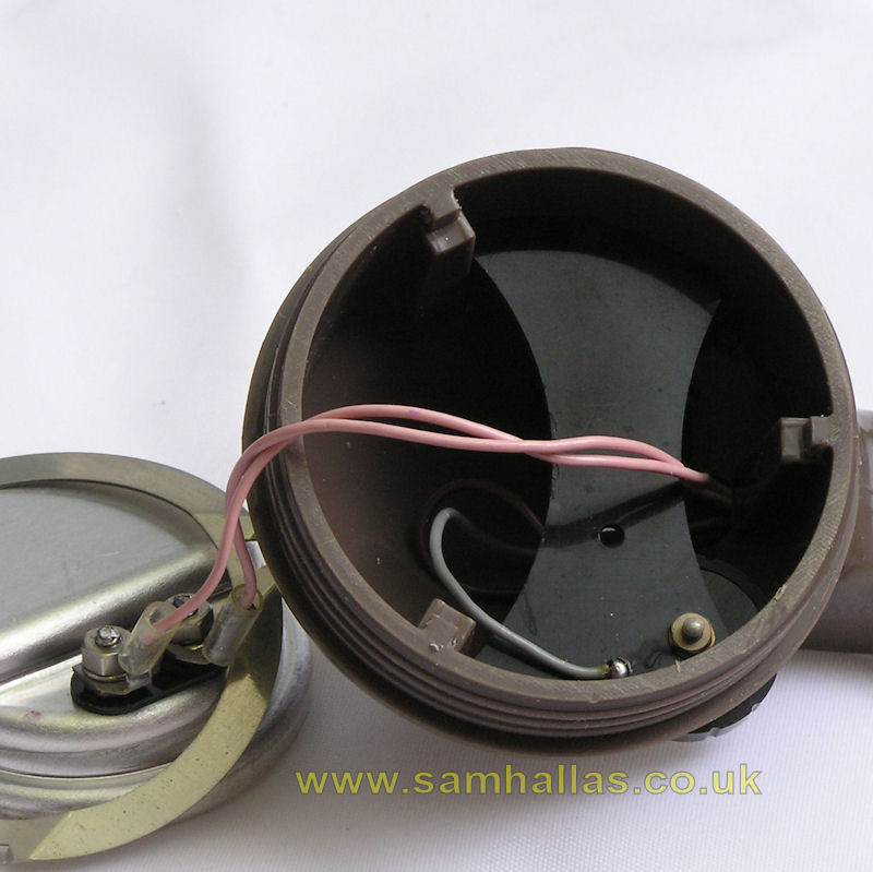

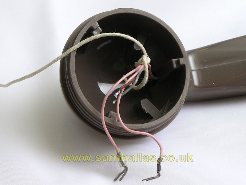
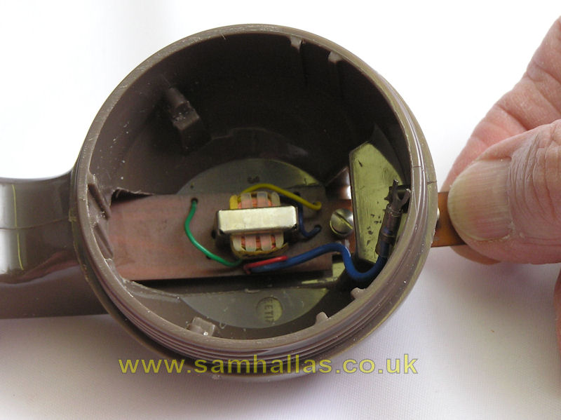
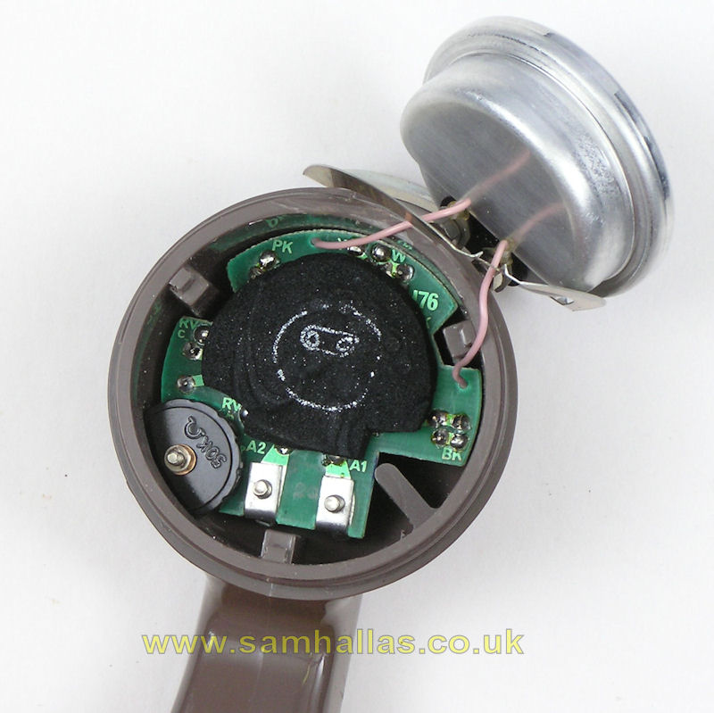
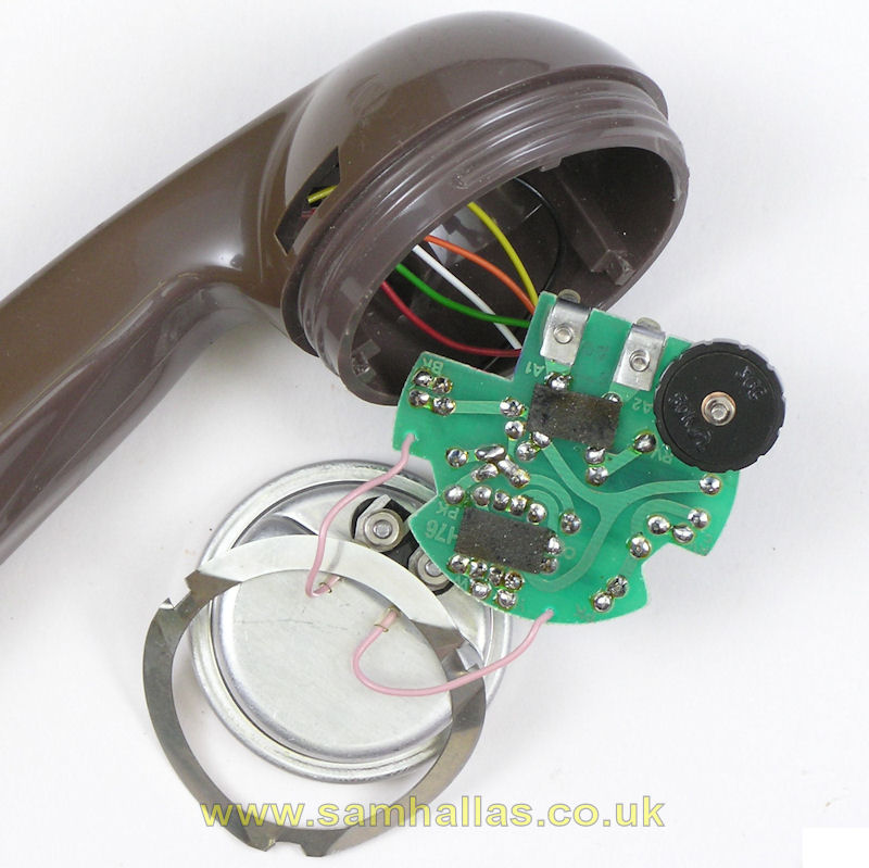
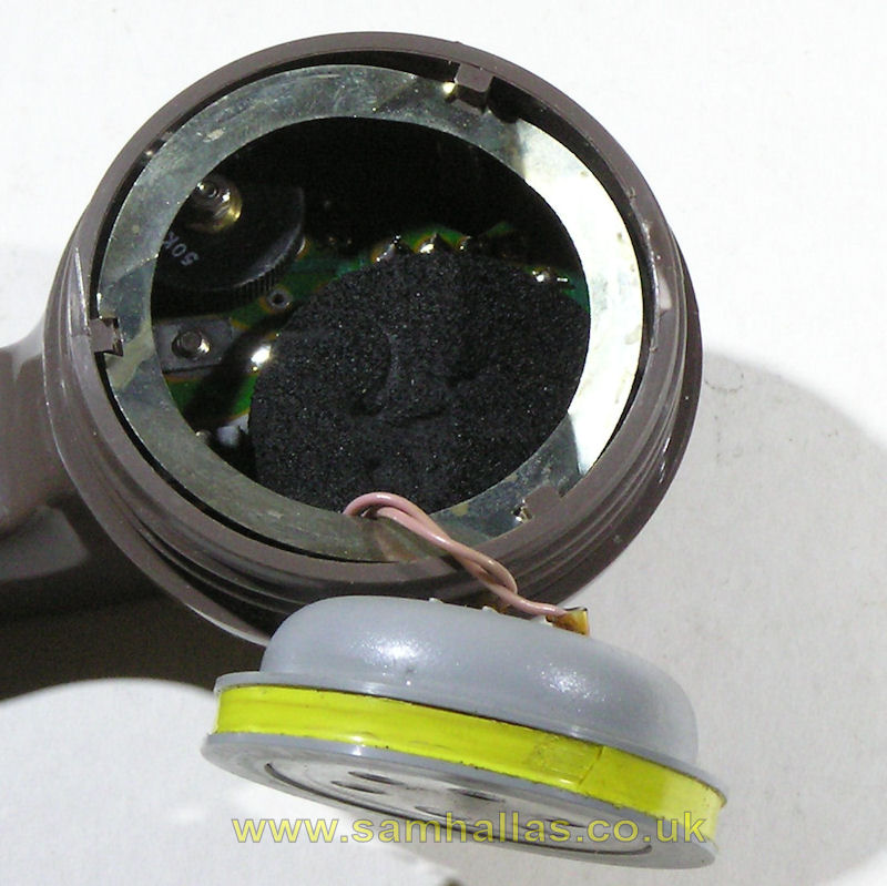
The rotary volume control is mounted on a plastic plate that sits inside the receiver cavity of the handset (left). Pulling the spring ring out allows it to be lifted clear (right). The amplifier is mounted on a narrow strip of circuit board housed within the handset handle. In order to remove it, the receiver must be disconnected and the volume control unsoldered. It's also prudent at this point to tie a piece of string round the wires to make it easier to get them back in again. (below)
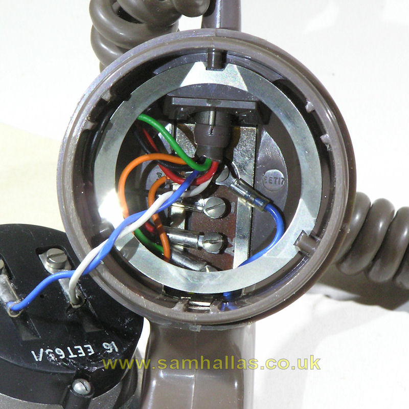
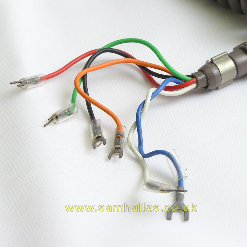
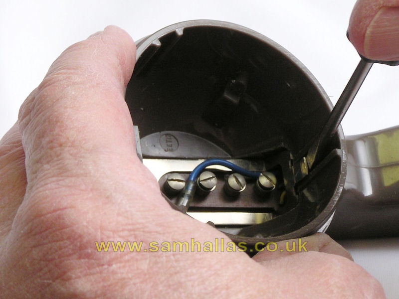
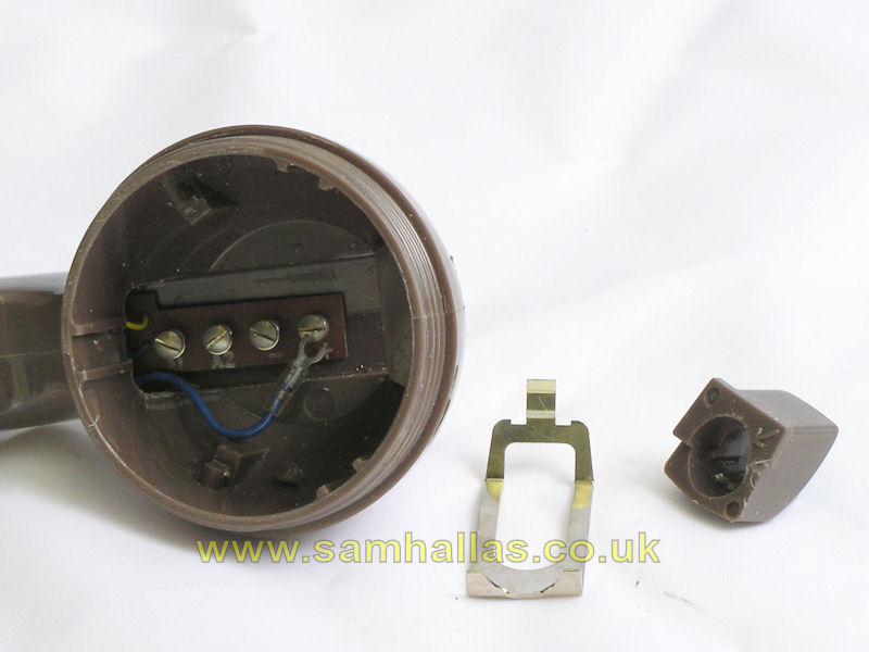
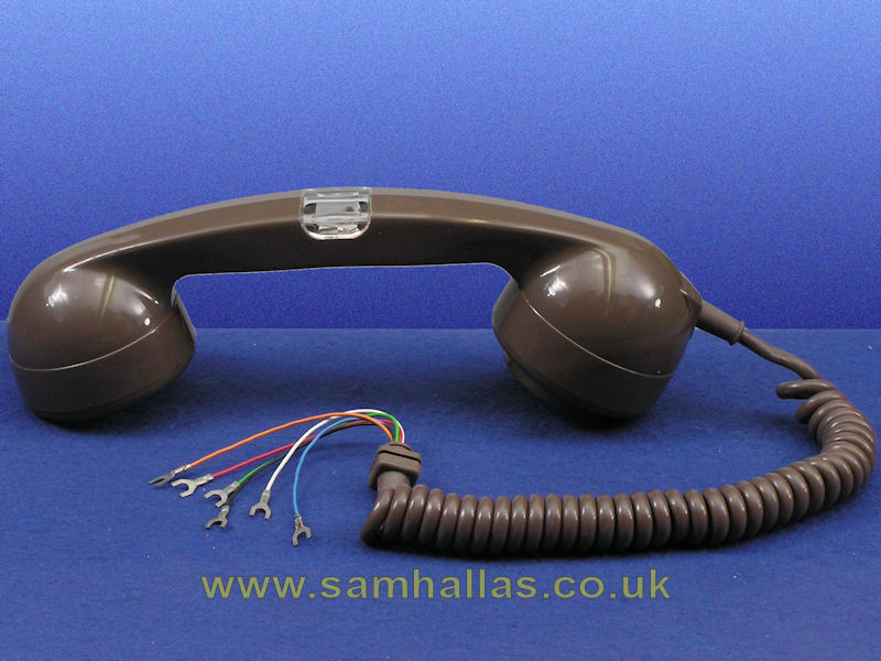
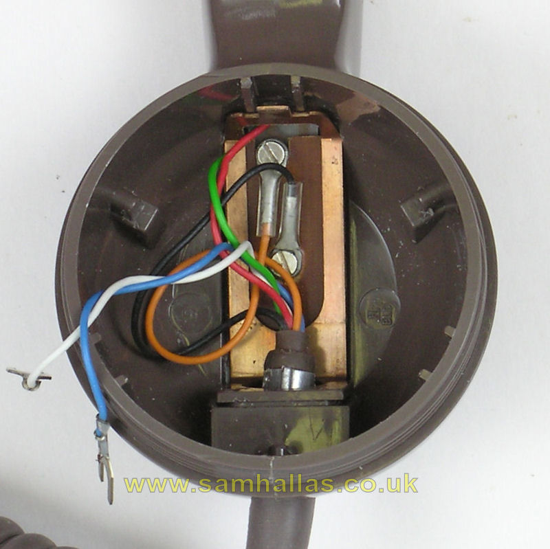
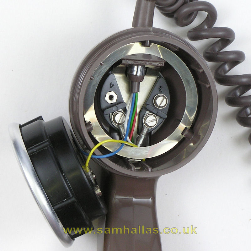
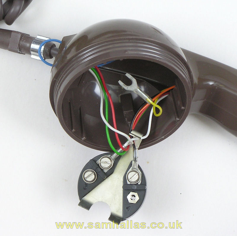
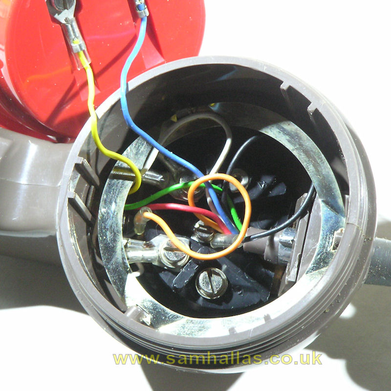
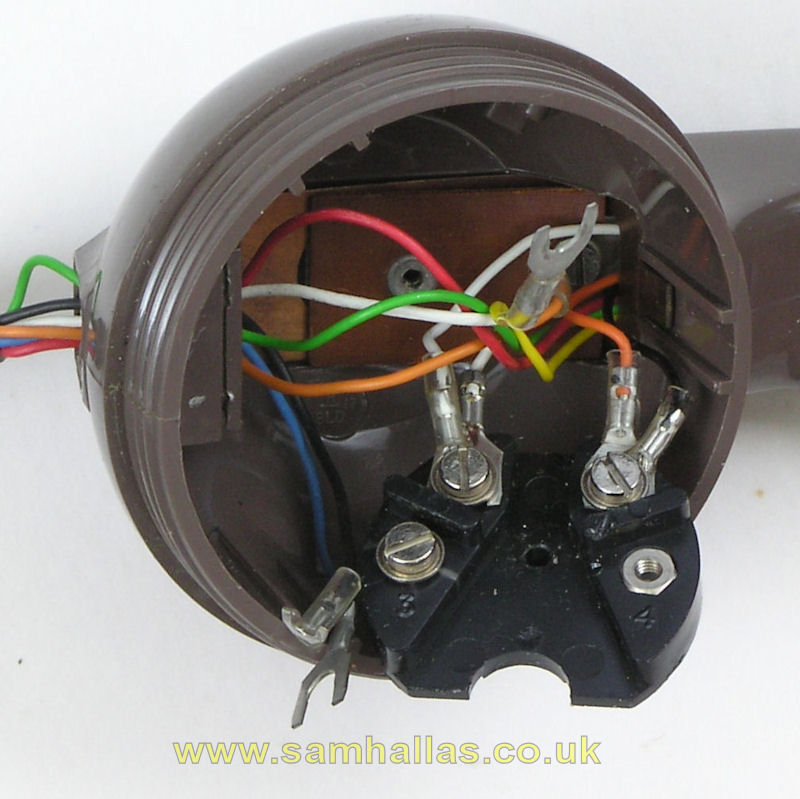
At the transmitter end of the handset there is a terminal strip fitted in the cavity (left). As this is a Handset No 5 the cord has two extra conductors, coloured orange and black which connect the battery to the amplifier. Handset No 4 has the normal four conductors, but still has a terminal strip. Note that the crimped terminals that connect to the strip have smaller spades than those on the blue and white wires that connect direct to the transmitter (right). I shouldn't need to remind you to take a note of the wire colours before disconnecting them. The moulded block that anchors the cord is normally cemented in place, but in the Handsets Nos. 4 & 5 it is removable and is held in position by a spring clip contained in the transmitter cavity. This allows the circuit board to be inserted or removed. Disconnect the cord and remove it as described in the main article on Handset No 3. After disconnecting the transmitter and removing the spring ring, the spring clip can be released by levering gently with a screwdriver (below left) and the spring clip can be removed along with the moulded block (below right).
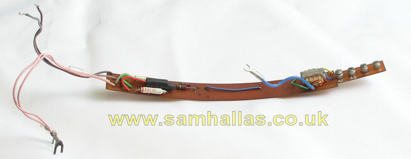
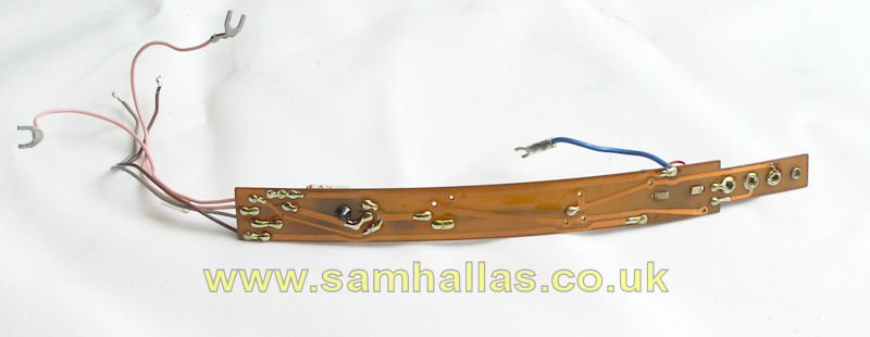
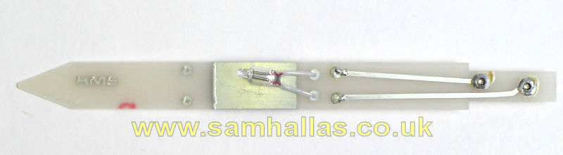
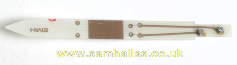
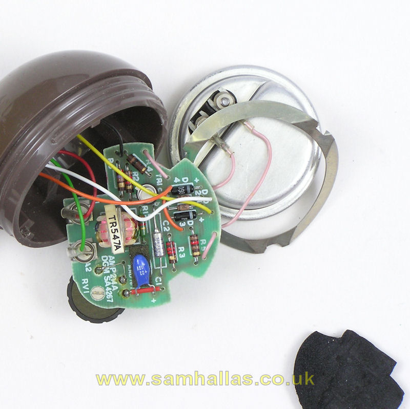
The circuit board can now be slid out carefully (left). There's not much to it (below), is there? Three resistors, two capacitors, a germanium transistor and a transformer for DC isolation. None the less it works well. The pink wires are from the receiver and the grey and brown wires are from the volume control. Look at the wiring side of the circuit board and compare N1840 with N1841 and you'll see that the one circuit board supports both circuit designs. The central link on the Handset No 5 board replaces half of the bridge rectifier in the HS No 4 circuit and the blue link wire replaces the other half.
Handset No 6 is fitted with a changover microswitch operated by a button below the receiver. It is normally configured to cut out the transmitter when pressed to allow a private aside to be made. In that arrangement it is fitted with a standard 4-way cord. An alternative configuration for control of dictation equipment requires a 6-way cord.
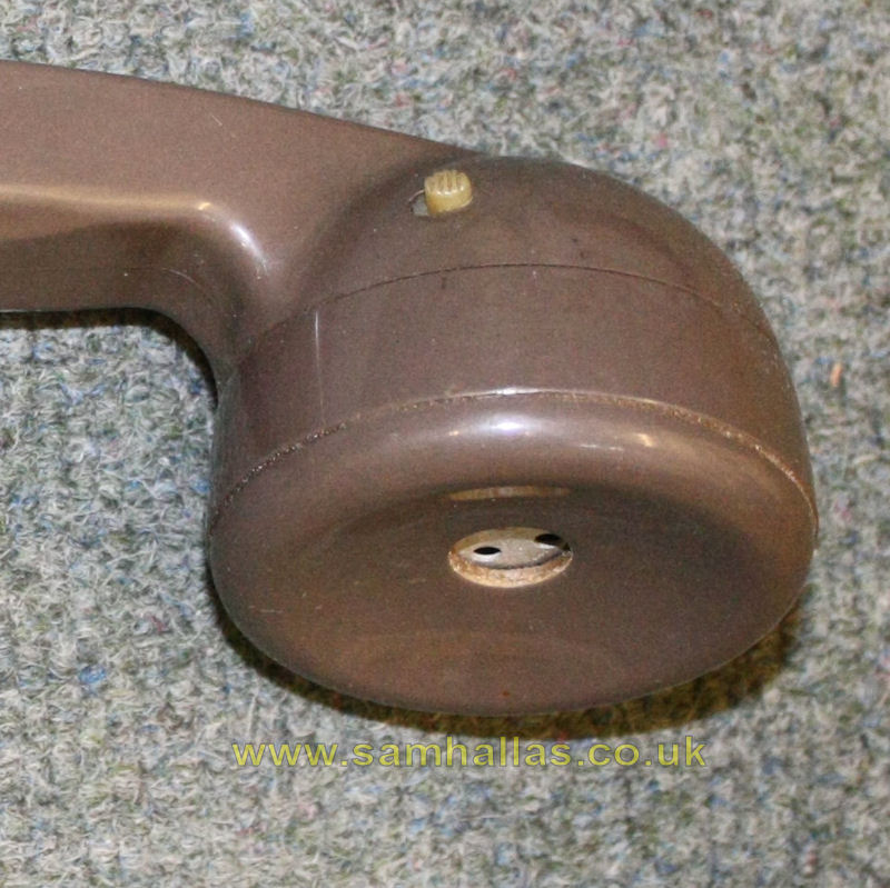
This sample was spotted at the auction of the late Norman Pearce's collection in March 2010. I was able to put it on the carpet and take a quick picture during the viewing session prior to the auction.
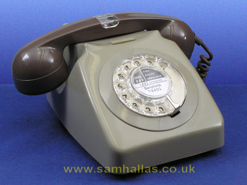
Here is a handset No 7 sitting on a grey Telephone No 746. Like the Handset No 5 above it has a cord with two extra conductors, coloured orange and black, to connect the lamp to the bell circuit. These can be seen in the right hand picture.
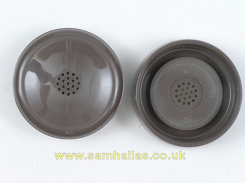
Once the caps are removed two other features become evident. The receiver cap is an Earpiece No 29A (left) which was introduced in 1981 to make the handset compliant with safety directives. The smaller perforations protect the user from dangerous voltages induced into the telephone circuit, whilst allowing the sound to escape. The transmitter is the newer, electronic Transmitter Inset No 21 (right). It contains an electret microphone transducer and an integrated circuit amplifier. The insets in this handset were both made by A.P. Besson of Hove, code DAE (now Hosiden-Besson). The transmitter is dated 1983
The neon lamp is mounted on a small printed circuit board which is fitted through the core exit hole described in the main article on Handset No 3. The procedure for removing it is the same as for the Handset Nos 4 & 5 described above.
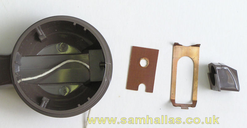
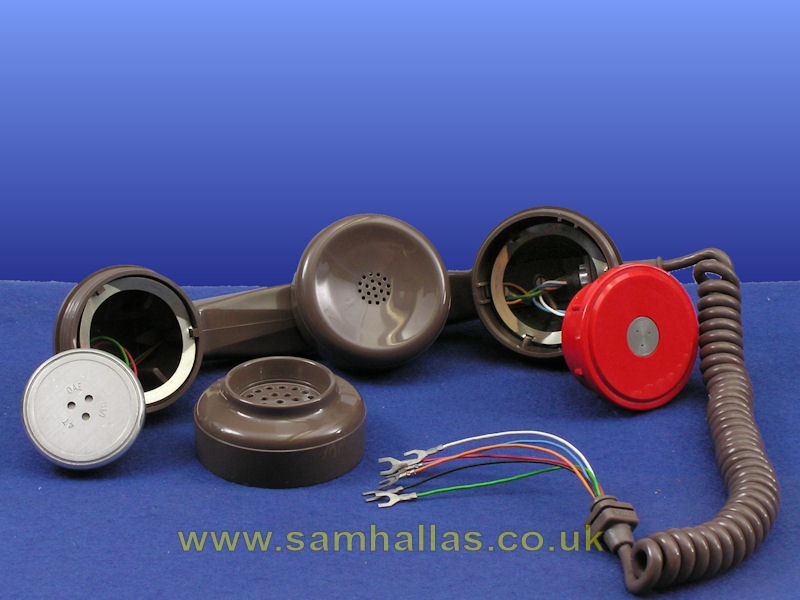
The transmitter cavity (left) contains the terminal strip for the circuit board which is insulated by a strip of plastic sheet. The clip that holds the core plug in place can be seen above the insulated sheet. The parts I removed can been in the picture to the right. Notice that one of the holes in the insulated sheet is not central, meaning it has to go back right way up. I put a piece of string through to make it easy to get the receiver wires back.
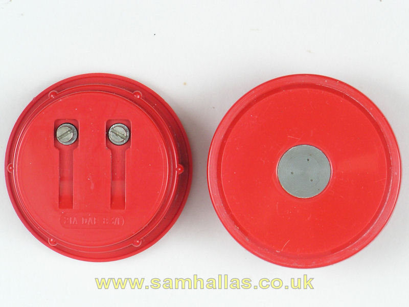
Here's the circuit board with the neon fitted behind a reflective strip. I assume that the upper end is pointed to make it easier to insert in the handset handle.
I found reassembling the Handset No 7 was tricky. This sequence seemed to be best.
First I threaded the cord wires through the handset body and the core plug. Then I threaded the red and green receiver wires through the retaining clip (there is a right and wrong way for this). I pulled the receiver wires with my piece of string through to the receiver cavity. It was now time to insert the neon circuit board. Because it tends to catch on the clear window you have to press it down as it goes in to smooth its passage. I terminated the orange and black wires on the neon circuit board before pressing the core plug and retaining clip back into place and pushing the cord grommet back. Finally I terminated the receiver and transmitter wires and screwed both earpiece and mouthpiece back.
Not surprisingly, Handset No 14A has the same external appearance as Handset Nos 4 & 5. However inside there are significant differences. The first thing that is evident without taking any of the covers off, is that it only uses a standard 4-way cord. A glance at N1842 shows that unlike Handsets Nos 4 & 5, this can be used either fed from line current or a local battery.
Looking inside the transmitter cavity reveals the small terminal block attached to the spring clip that fits under the core plug (left). The arrangement is clearer with the transmitter disconnected and the spring ring removed (right). You can see that the transmitter is fed in series with the amplifier: the blue wire from the cord connects direct to the transmitter; the other side of the transmitter connects to the yellow wire feeding up the handle to the amplifier; the return current returns on a white wire from the amplifier and into the white wire to the cord.
Opening the receiver cavity reveals the amplifier nestling under a protective foam pad (left). The amplifier is kept in place by pressure from the receiver 4T and simply lifts out (right). Amplifier No 214A is slightly more sophisticated, but still only a single transistor (back view below). This version is marked as being made by AAD, Astralux Dynamics, Brightlingsea.
Handset No 17A combines the neon lamp of Handset No 7 with the amplifier of Handset No 14A. One drawback of this is that it is of necessity line powered since there aren't enough conductors in a handset cord to feed the battery power.
Opening the transmitter cover reveals a terminal block similar to that in Handset No 14A (left), but this one is not attached to the spring clip. Instead is held in place by the screw holding the black wire from the cord. As with Handset No 14A you can see in the picture on the left that the transmitter is in series with the amplifier just like it is in Handset No 14. With the transmitter disconnected and the spring ring removed I can take out the screw holding the black wire and pull out the terminal block to be seen more easily (right).
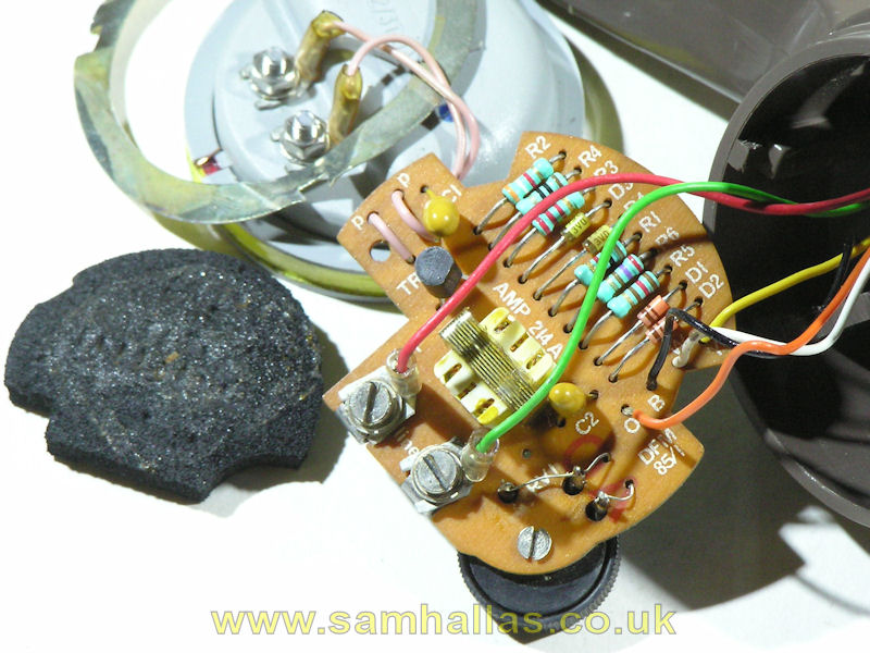
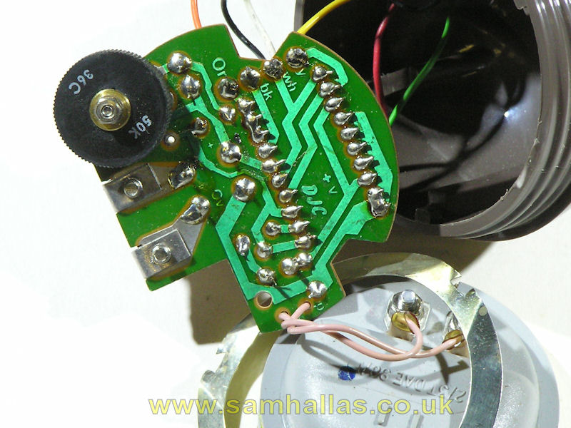
The same arrangement used in the Handset No 14A applies at the receiver end. The receiver rests on a foam pad (left) underneath which is an Amplifier No 214A (right). This one is a different physical design although made to the same circuit, SA 4267. It's marked DFM, made by Denis Ferranti Meters in Bangor, N. Wales. (Back view below)
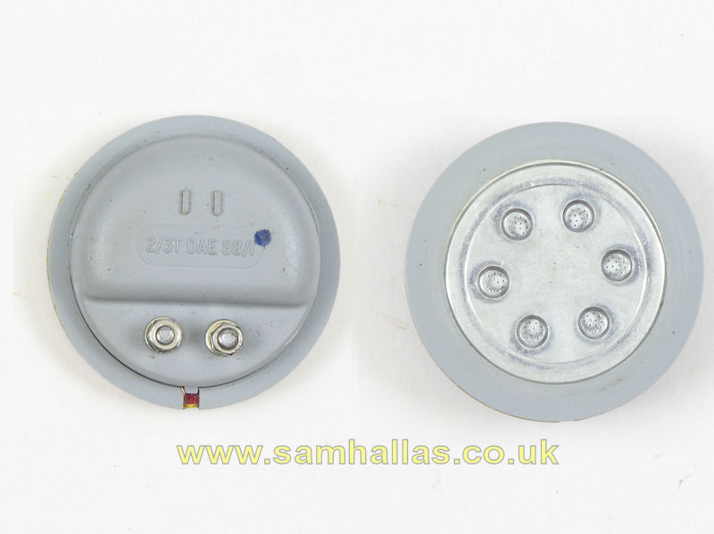
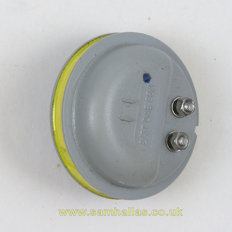
If you look at the left hand picture above, you'll see that the receiver is not the Receiver Inset No 4T used in all the other models of handset so far, but is a variant of the Receiver inset No 3T with a coupling coil for inductive loop connection with hearing aids (right), designated Receiver Inset 2/3T and made by Hosiden-Besson (Code DAE) in 1988. The basic receiver is the same size as a normal 3T, but with the coil wound round it becomes the same diameter as its big brother, the 4T.
Handset Nos 4 & 5 www.britishtelephones.com/hands4.htm
Similarly:
Handset No 6
Handset No 7
Handset No 14A
Handset No 17A
