
Sam Hallas' Website
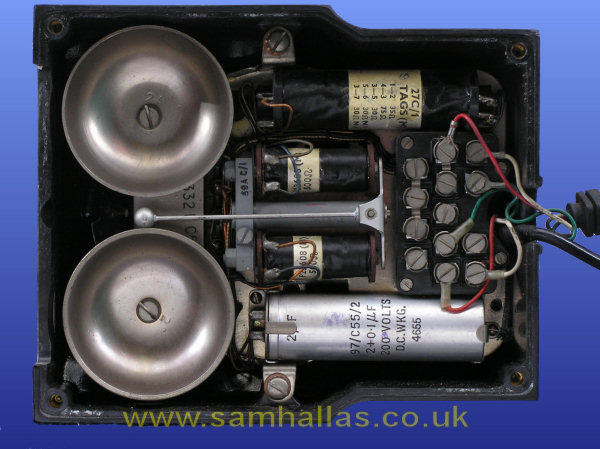
With the base removed the significant difference from previous telephones becomes obvious: the 300 series telephone has an internal chassis. All the components except the dial are mounted on the chassis which is held in place by the three captive 2BA screws with shakeproof washers, centre top and bottom and just right of the capacitor in the picture.
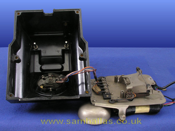
The bell gongs are held by two 2BA screws and have a shakeproof washer between the gong and the chassis. The gongs are slightly eccentric to allow them to be adjusted for optimum ring. They have different tones to produce that characteristic British jangling bell sound. I took them off at this point to make the chassis more manageable.
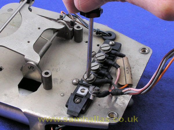
Now is the time to disconnect the cords. The dial cord is connected to the terminal block on top of the chassis with 4BA cheese head screws and washers through wire-wound loops (Fig 8). With the bells towards you they go blue, slate, brown, pink orange from left to right. The line cord goes: White on 1, Green on 2, Red on 9. The handset cord goes: White on 4, Green on 6 and Red on 5. The cords are anchored to the support pillars for the terminal block by their laces (Fig 9).

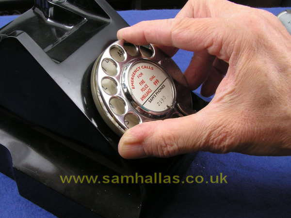
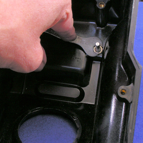
The dial can now be removed from the main case. Notice the cunning groove at the front which allows a long screwdriver to reach the dial retaining screw (Fig 10). With the dial terminals away from you, the colour sequence is the same as on the chassis terminal block, blue, slate, brown, pink, orange. Take the dial retaining screw completely out, turn the case right way up and twist the dial slightly anti-clockwise to release it (Fig 11).
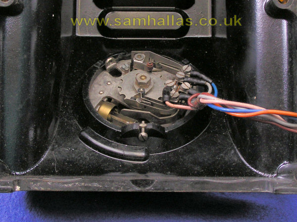
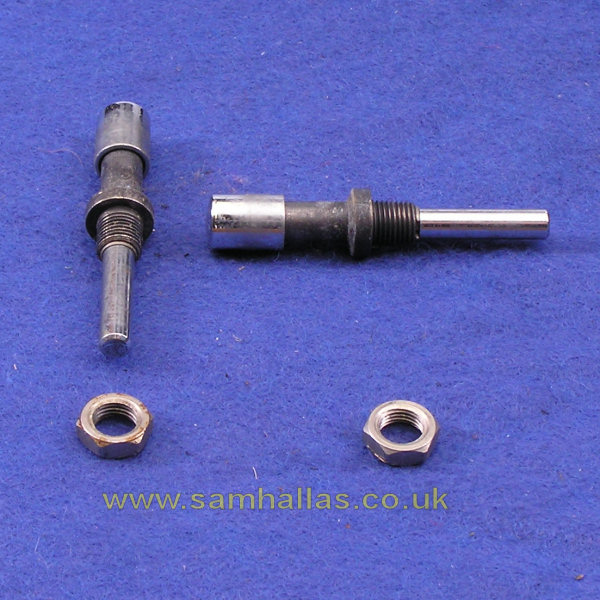
Turn the case over again and remove the cradle rest plungers by undoing the 1BA nuts holding them in place (Fig 11). They are fairly inaccessible in normal use and so can benefit from a rub over with a nailbrush to clean them. Each plunger is prevented from pulling out of its sleeve by a small circlip.

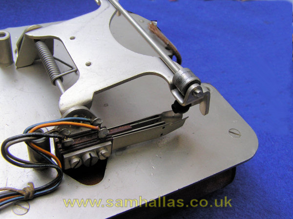
Let's have a look at the chassis now (Fig 14). The upper side has the cradle spring mechanism which comprises a rocking platform pivoted at one end on a steel rod with a torsion spring. The other end has a similar steel rod with a roller at each end, acted on by the cradle rest plungers. The rollers prevent any tendency of the cradle mechanism to stick. The rods are split at the end and spread to stop them sliding out. Both sides of the platform have a protrusion which acts as a stop to limit travel. One side has an insulated peg (Fig 15) which moves between the hook switch contacts, opening the circuit when the handset is on hook. The hook switch springset is held together by the two outer 8BA screws and is fixed by the centre 6BA screw. The springset is constructed similarly to that on Telephone No 162.
Early models of the 300 Series had a flat platform without the rollers or end stops and used differently shaped plungers. The design was changed because of sticking. (Ref 3).
The dial cord terminal block is held in place by two 6BA dome head screws. The left hand screw also holds a spring clip intended to restrain the dial cord so it doesn't interfere with the dial mechanism. I have yet to see a phone where it's been used. Just above the terminal block in the picture you can see the 4BA screws which hold the bell in place. To the right hand side are the countersunk 6BA screws holding the induction coil, which are rather obscured by a cradle rest roller and the hook switch cable.
The tapped pillars, roughly central, are for mounting the accessory switches and rectifier element on other models. The hank bushes at the bottom of the picture are for the bell gong screws. I guess that these are needed because the thickness of the chassis doesn't provide enough thread depth to hold the bells tightly.
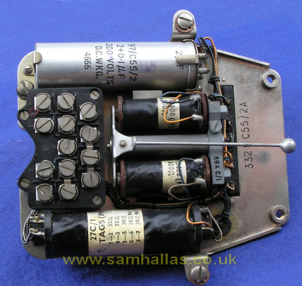
The underside of the chassis contains all the remaining components and the terminal block which links them all together. The design is remarkably compact, using composite components to good effect. The induction coil (Coil, Induction No 22 up to 1943 and 27C thereafter) contains not only the three anti-sidetone windings, but also the two non-inductive 30 ohm resistors. The capacitor (Condenser, MC No 97) is a double unit holding both the main 2 µF bell capacitor and the 0.1 µF auxiliary capacitor to provide radio frequency immunity. The only other component is the bell (Bell No 59A, unmounted).
All the components can be unscrewed. We saw the screws for the bell and induction coil on the top of the chassis. The tubular capacitor is held by metal clips retained by two 6BA screws. Some models have a rectangular bodied capacitor. The terminal block is held by four countersunk 6BA screws into tapped pillars. Sadly the chassis cannot be cleared of components completely without unsoldering some of the wires. Sorry, I'm not going to do that with this phone.
The terminal block provides various flexibility points of removable links for the common variations of what the Post Office called Plan Working. Complete telephones with individual numbers were also issued for specific applications. Let's have a look at some examples I have available.
The handset is Telephone No 164 and it has its own article Handsets I Have Known - Telephone No 164
 Previous
Next
Previous
Next