
Sam Hallas' Website
The sixth in a series of articles where I dismantle a telephone to show its construction and make my own comments on the design and choice of material
Click the small images for pop-up larger version.
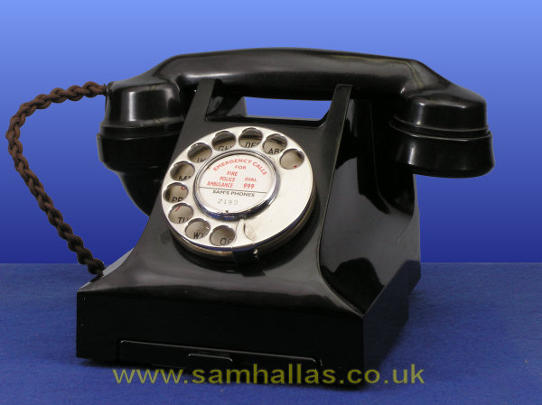
The 300 Series Telephone is the first British Post Office design to incorporate all components into a single body. The case design had a smooth modern appeal building on the sweeping curves introduced in its predecessors. The main body is a single moulding in the wonder thermo-setting plastic, Bakelite.
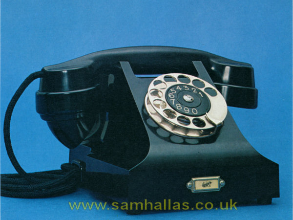
The 300 Series of telephones were the successors to the Telephone No 162 and 232, the pyramid-shaped phones introduced in 1929 and 1934 respectively. Both required a separate bell set. However by 1931 LM Ericsson of Sweden were already marketing a one-piece telephone. In addition, their "telephone differed from earlier models in that . the handset did not rest in a moving cradle, as before, but in a fixed seating in the case." [Ref 1]. The case design was by Jean Heiberg, Professor in Oslo's National Academy of Arts.[Picure: LM Ericsson by permission]
In adapting the telephone for the British market the Post Office chose to use the already well-established handset, Telephone No 164, rather than the Ericsson style. Other changes in the Anglicising were a switch to rear-entry plaited cables, and the addition of an optional drawer for dialling instructions. The dial was the standard BPO Dial No 10.
The British Post Office was not entirely convinced that a single piece telephone was needed for domestic use. It felt that the combined telephone and bell set would be more suitable for businesses. It took the GPO until 1936/1937 to introduce the basic model, Telephone No 332. It has been suggested that the delay was to allow the various British manufacturers to set up their production lines.
There was a variety of models in the 300 Series for different applications (Ref 2). The telephone in the picture is Telephone No 332, the basic model for residential use. I'll be looking at others in the range: Telephone 330, the model for Private Branch Exchange use with a recall button; Telephone 312, with a similar single button, but for shared service lines; and an Ericsson N1365CB, a model without a dial made for non-GPO customers, but with identical circuitry.
Let's start by turning the telephone over and looking at the base. (Fig 3)
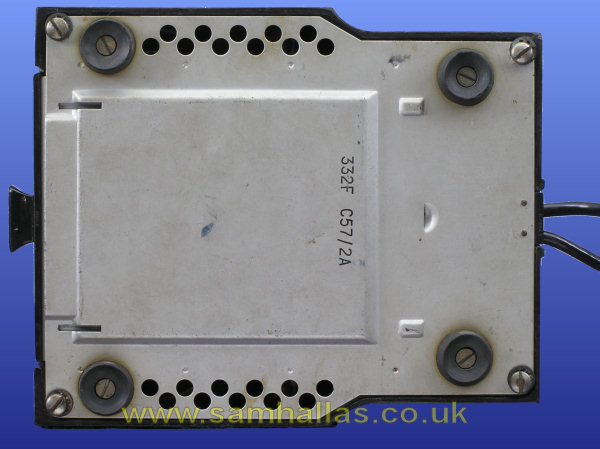
The markings tell us that this is a Telephone 332 F - a residential model with an all-figure dial. (OK you'll have spotted that it had a dial with letters and numbers in the first picture: it must have been changed at some time.) The letter C and the number 57 tell us it was manufactured by GEC at Coventry in 1957 - fairly late in the life of the 300 Series. It's a Mark 2A, which was the last model produced. As befits such a late model it has been fitted with plastic cords instead of the earlier plaited cotton-covered cords. The desk cord is in fact the type used for the later Telephone No 706, which may have been fitted in error. I replaced the desk cord with a plaited one when I reassembled the phone.

The base is secured by the four captive 2BA screws in the corners through tapped holes in the steel pressing. (Do I need to remind you that I like captive screws?) Under the screw heads are shakeproof washers to reduce the risk of the screws coming loose in service. The base has shaped indentations to hold the drawer with holes which I presume are to improve audibility of the internal bell. The steel is painted a silver colour. Another in my collection is grey/ green.
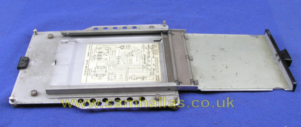
The upper side of the base has a circuit diagram pasted in the area covered by the drawer (Fig 4). The drawer guides are also of steel spot welded to the main base. On another phone I found the circuit had been silk-screen printed onto the painted surface. The drawer is of identical construction to the one used on Telephones No 162 and 232.
The rubber feet are fixed in a similar manner to those on the Tele 232. They have an integral washer and the 4BA shoulder screws have plain sections of shank to stop them crushing the feet. The screws are held in place by plain nuts, but, curiously, no washers. A subtle touch is that the nuts are flat at the bottom and chamfered at the top. The small plastic block at the rear applies pressure to the handset and desk cord to prevent them being pulled out. It's held in place by two countersunk 8BA screws. (Fig 5)
